Display device and portable electronic device

a technology applied in the field of electronic devices and display devices, can solve the problems of difficult downsizing of hinges and a change in design, affecting the design of multiple display units, and not revealing the transmission of display data to a plurality of displays, so as to increase the degree of design freedom and reduce the size of the device

Active Publication Date: 2009-08-11
GK BRIDGE 1
View PDF14 Cites 11 Cited by
  • Summary
  • Abstract
  • Description
  • Claims
  • Application Information

AI Technical Summary

Benefits of technology

[0010]It is an object of the present invention to provide a display device and portable electronic device which decrease by a simple circuit configuration the number signal lines for connecting a plurality of displays and their display control circuits, thereby downsizing the device and increasing the degree of freedom in design.

Problems solved by technology

Many signal lines must be passed through the hinge, which makes downsizing of the hinge and a change in design difficult.
Since the number of connector terminals increases in accordance with the number of signal lines, it also becomes difficult to downsize the printed wiring board and housing.
This technique does not disclose transmission of display data to a plurality of displays by using a common signal line.
Time division transmission requires a time division multiplexing process, resulting in a complicated process and expensive device.

Method used


Image

  • Display device and portable electronic device
  • Display device and portable electronic device
  • Display device and portable electronic device

Examples


first embodiment

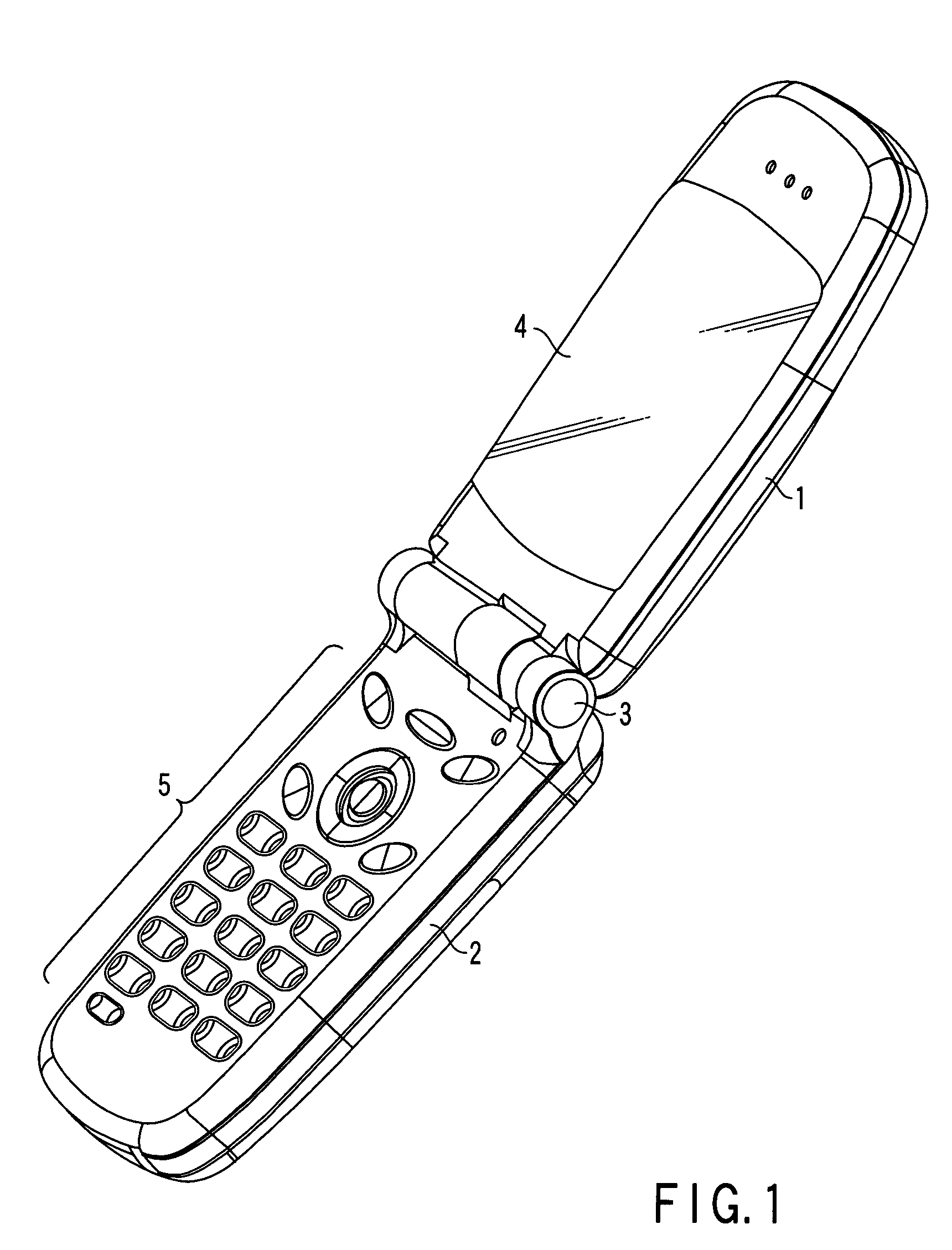
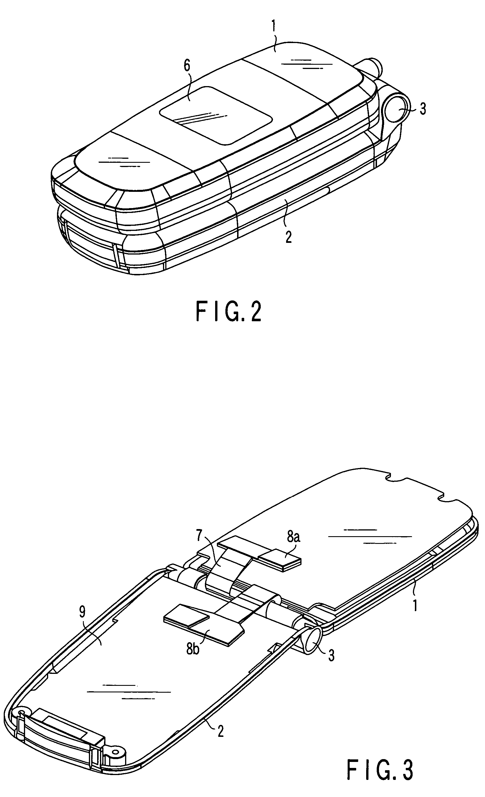
[0035]FIGS. 1 to 3 are perspective views showing the outer appearance of a portable electronic device having a display device according to the first embodiment of the present invention. The portable electronic device of the first embodiment is a so-called foldable portable communication terminal formed by pivotally connecting an upper housing 1 and lower housing 2 via a hinge mechanism 3. FIG. 1 shows a state in which the housings 1 and 2 are open, and FIG. 2 shows a state in which the housings 1 and 2 are closed. FIG. 3 is a perspective view showing the internal structures of the upper housing 1 and lower housing 2.

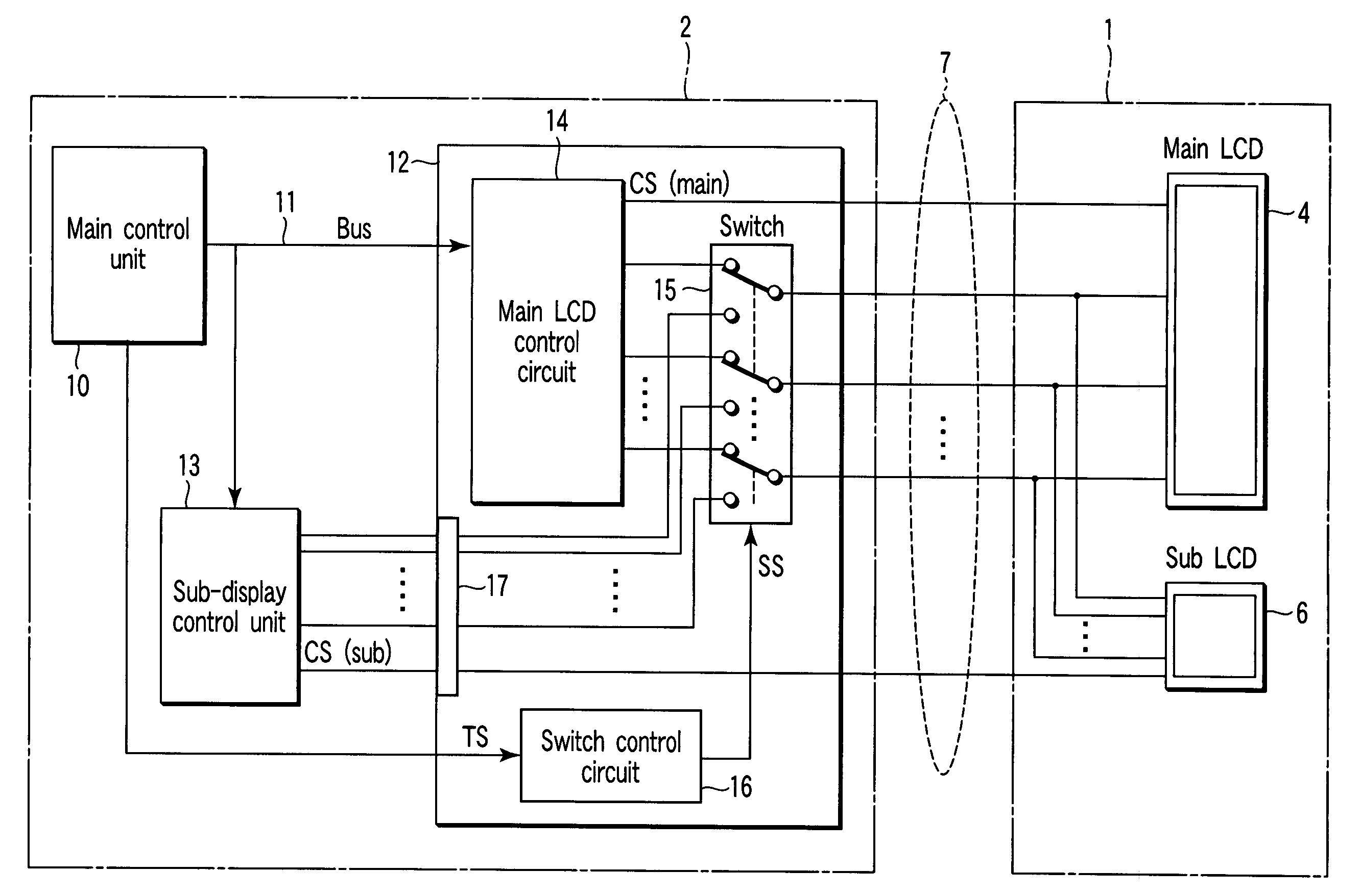
[0036]The upper housing 1 comprises a main LCD (Liquid Crystal Display) 4 on the front surface and a sub-LCD (Liquid Crystal Display) 6 on the rear surface. The lower housing 2 incorporates a main printed wiring board 9 together with a key input device 5 and the like. The main printed wiring board 9 supports a main control unit 10, main display control unit 12, and sub-d...

second embodiment

[0064]FIG. 7 is a block diagram showing the circuit configuration of a portable communication terminal according to the second embodiment of the present invention. In FIG. 7, the same reference numerals as in FIG. 4 denote the same parts, and a detailed description thereof will be omitted.

[0065]An upper housing 1A comprises display buffers 21 and 22 in correspondence with a main LCD 4 and sub-LCD 6. The display buffers 21 and 22 hold display data supplied from a main LCD control circuit 14 and sub-display control unit 13 via a signal line cable 7. The display buffers 21 and 22 keep supplying the held display data to the main LCD 4 and sub-LCD 6 to continue display even after the signal line cable 7 is disconnected.

[0066]This configuration can realize the following display operation. For example, when the portable communication terminal receives an incoming signal while the housings 1 and 2 are open, termination notification display data must be displayed on both the main LCD 4 and s...


PUM


Abstract

A display device includes first and second displays, first and second display control circuits which respectively control the displays, and a signal transmission path which is shared between the first and second displays and has one system of signal lines. The display device further includes a switching circuit for the signal transmission path and a switching control circuit for the switching circuit. The switching control circuit performs switching control of the switching circuit in synchronism with display control by the first and second display control circuits. The first display and first display control circuit, and the second display and second display control circuit are alternately connected by the signal transmission path.

Description

CROSS-REFERENCE TO RELATED APPLICATIONS[0001]This application is based upon and claims the benefit of priority from prior Japanese Patent Application No. 2004-232514, filed Aug. 9, 2004, the entire contents of which are incorporated herein by reference.BACKGROUND OF THE INVENTION[0002]1. Field of the Invention[0003]The present invention relates to a display device having a plurality of displays and a portable electronic device having the display device.[0004]2. Description of the Related Art[0005]Recently, most portable electronic devices comprise a display device having a plurality of displays. For example, a foldable portable terminal formed by pivotally connecting first and second housings via a hinge has a main display on the front surface of the first housing and a sub-display on the rear surface of the first housing. The main display displays all display data such as transmission / reception data, telephone book data, and various control information representing the operating st...

Claims


Application Information

Patent Timeline
Patent Type & Authority Patents(United States)
IPC IPC(8): G09G5/00
CPCG06F3/1438H04M2250/16H04M1/0245H04M1/0214
Inventor NOHARA, KOICHI
Owner GK BRIDGE 1
Why Eureka
Try Eureka