Safety switching device and method for failsafe shutdown of an electric load

a safety switching device and electric load technology, applied in the direction of resistors, emergency protective arrangements for limiting excess voltage/current, non-adjustable resistors, etc., can solve the problems of contactor coils that decay more slowly, the level can substantially exceed the normal operating voltage, and the overvoltage spike occurs, so as to increase the thermal load of the safety switching device and facilitate the installation of the novel safety switching device

Inactive Publication Date: 2009-08-11
PILZ (COMPANY)
View PDF17 Cites 24 Cited by
  • Summary
  • Abstract
  • Description
  • Claims
  • Application Information

AI Technical Summary

Benefits of technology

[0015]The invention is thus based on the idea of designing the anti-surge element to be variable. This makes it possible to design the anti-surge element differently for different situations and requirements and to optimize it in each case to the intended use. The anti-surge element thus has different anti-surge operating modes, which can be activated depending on the intended use and situation.
[0034]This refinement makes it easier to install the novel safety switching device, since the anti-surge element does not need to be wired from the user side in addition to the safety switching device. On the other hand, it is here possible to integrate the anti-surge element into the safety switching device without unduly increasing the thermal loading of the safety switching device.

Problems solved by technology

Therefore, prior art safety switching devices are generally of a redundant design and, in numerous countries, they require special approval from a competent supervisory authority.
This means that, during shutdown, an overvoltage spike occurs, whose level can substantially exceed the normal operating voltage.
However, the anti-surge elements in the known safety switching devices have two principal disadvantages which may be significant to differing extents depending on the practical implementation.
A first disadvantage consists in the fact that the current through the contactor coil decays more slowly during shutdown, which delays the shutdown operation.
A second disadvantage is undesirable introduction of heat into the safety switching device, which is produced, in particular, by the signal processing part needing to switch the output-side switching elements off and on again frequently for test purposes.

Method used


Image

  • Safety switching device and method for failsafe shutdown of an electric load
  • Safety switching device and method for failsafe shutdown of an electric load
  • Safety switching device and method for failsafe shutdown of an electric load

Examples


Embodiment Construction

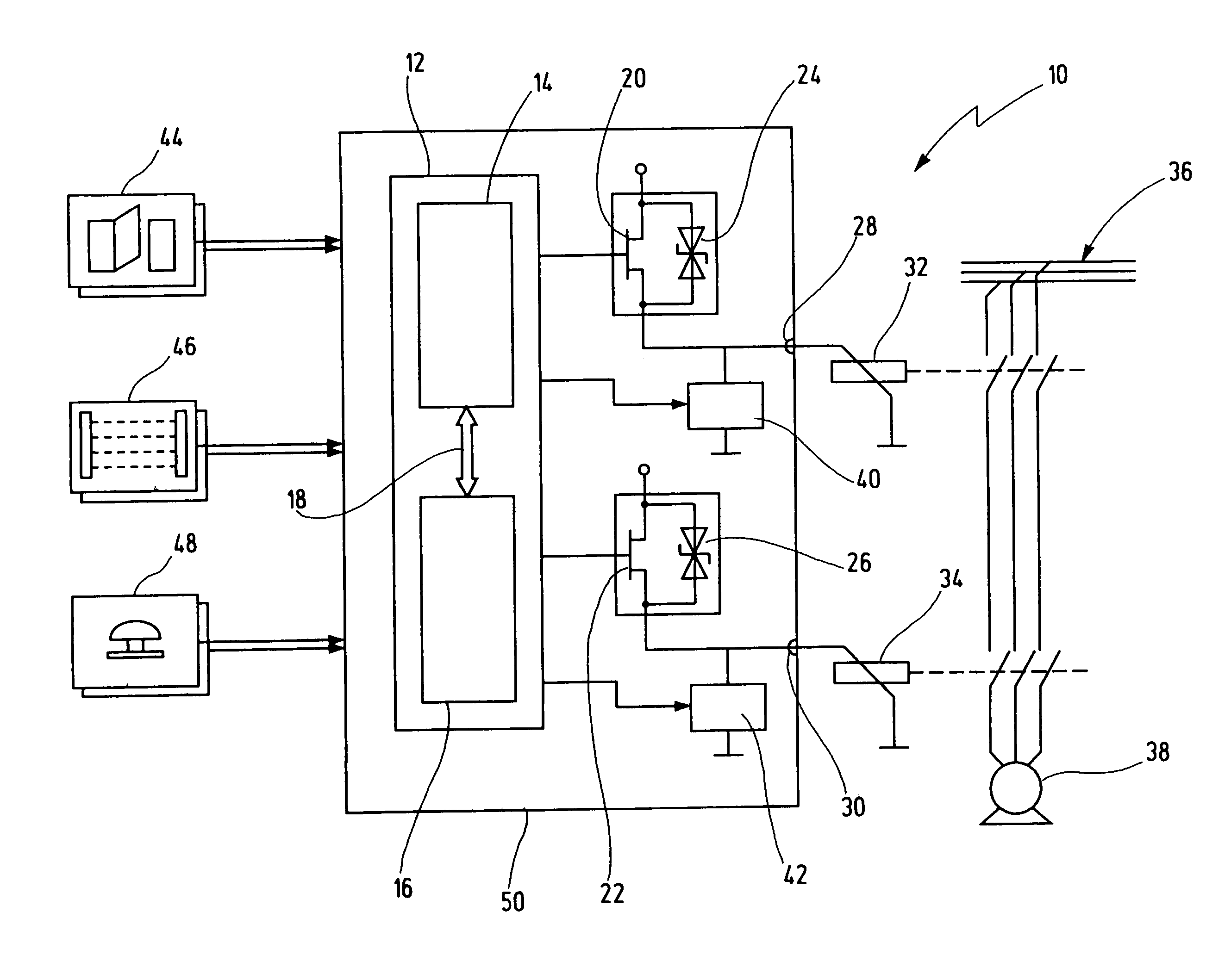
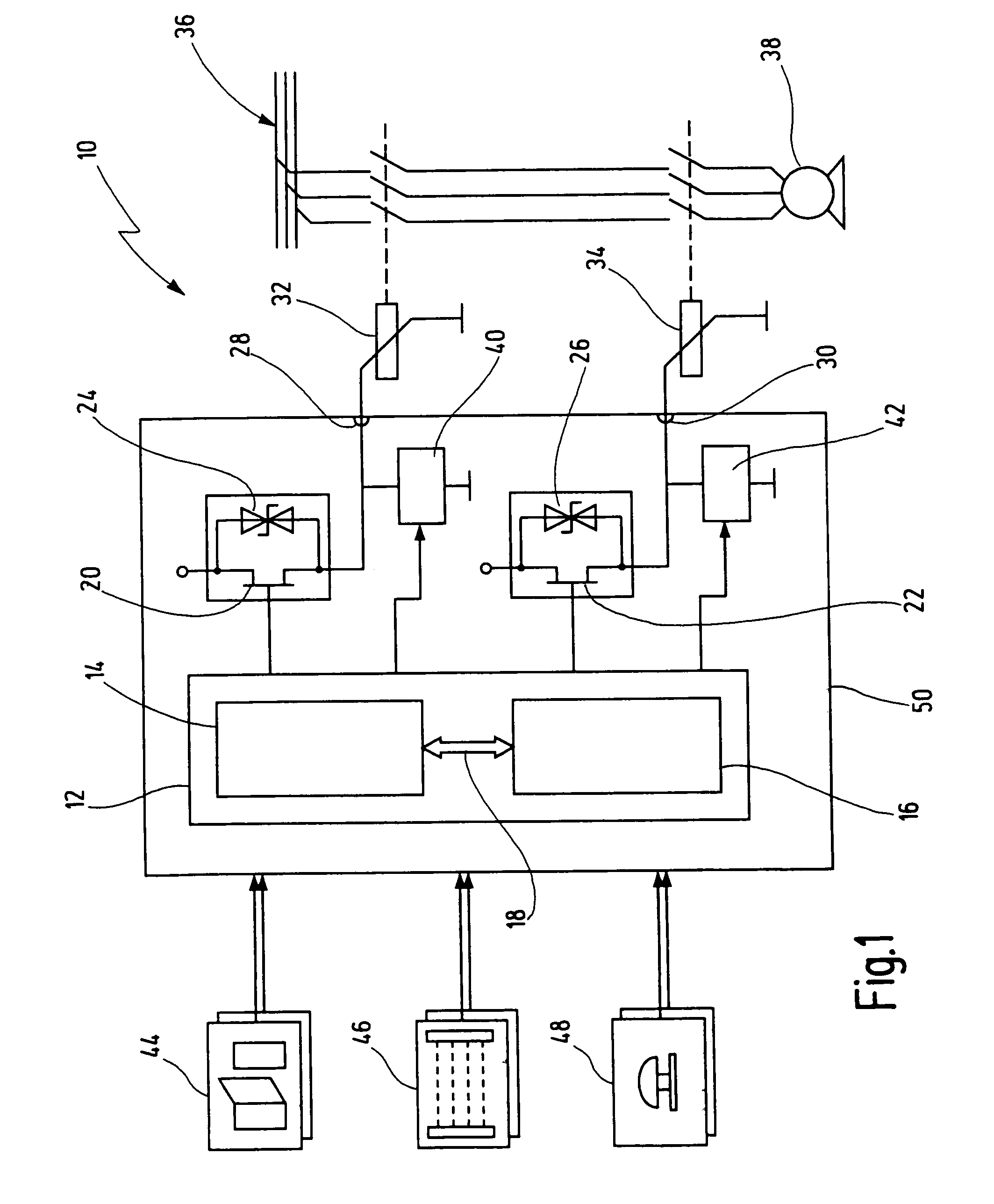
[0041]In FIG. 1, an exemplary embodiment of a novel safety switching device is overall given the reference numeral 10.

[0042]The safety switching device 10 has a signal processing part 12, which is here illustrated in simplified form with two redundant microcontrollers 14, 16. The two redundant microcontrollers 14, 16 monitor one another, as is indicated by an arrow 18. It goes without saying that each of the two microcontrollers 14, 16 has a suitable peripheral (memories, communication interfaces etc.), which is not illustrated here for sake of simplicity. Furthermore, more than only two redundant channels may also be provided for the signal processing.

[0043]The safety switching device 10 has two redundant, output-side switching elements 20, 22, which are illustrated here as electronic switching elements (semiconductor components, in this case MOS transistors) in accordance with a preferred embodiment. In the case of such switching elements, the advantages of the present invention c...


PUM


Abstract

The invention relates to a safety switching device for the failsafe shutdown of an electric load, such as an electrically driven machine. The safety switching device has a signal processing part for receiving and evaluating an input-side switching signal, which, for example, originates from an emergency stop switch. It also has at least one switching element which, controlled by the signal processing part, provides an output-side switching signal for shutting down the load. An anti-surge element is provided for canceling reaction voltage spikes when the load is shut down. The anti-surge element has at least a first and a second anti-surge operating mode, which can be activated as an alternative to one another.

Description

CROSS-REFERENCES TO RELATED APPLICATIONS[0001]The present application is a continuation of co-pending international patent application PCT / EP2004 / 004352, filed on Apr. 24, 2004 and published as WO 2004 / 105067 A1 in German language, which international application claims priority under the Paris convention from German patent application 103 25 363.7, filed on May 23, 2003.BACKGROUND OF THE INVENTION[0002]The present invention relates to a safety switching device and a method for the failsafe shutdown of an electric load, in particular for shutting down an electrically driven machine. The invention particularly relates to a safety switching device and a method for the failsafe shutdown of an inductive load that causes overvoltage spikes when being shut down.[0003]Safety switching devices in terms of the present invention are provided for controlling technical systems and devices in a failsafe manner, and in particular shutting them down in a failsafe manner, if required, in order to p...

Claims


Application Information

Patent Timeline
Patent Type & Authority Patents(United States)
IPC IPC(8): H02H3/22H01H47/00H02H9/04
CPCH02H9/047H01H47/004
Inventor HORNUNG, GUENTER
Owner PILZ (COMPANY)
Why Eureka
Try Eureka