
Arranging CELP information of one frame in a second packet

a technology of celp information and packet, applied in the field of integrated circuits, networking, systems and processes for packet communication, can solve the problems of packets being lost, delay jitter, and not only delayed, but also unable to reach their destination,

Inactive Publication Date: 2009-08-11
TEXAS INSTR INC
View PDF59 Cites 37 Cited by
  • Summary
  • Abstract
  • Description
  • Claims
  • Application Information

AI Technical Summary

Benefits of technology

The invention relates to a single-chip integrated circuit that includes a processor circuit and a source rate/diversity control. This control can be used for time diversity, path diversity, or combined time/path diversity. The invention also includes other processes, improved packets, and packet ensembles, as well as various computer add-in cards, information storage articles, systems, computers, gateways, routers, cellular telephone handsets, wireless base stations, appliances, and packet networks. The technical effects of the invention include improved data transmission and reliability in various communication systems.

Problems solved by technology

The technical problem addressed in this patent text is the issue of lost packets in Voice over Packet (VoP) and Voice over Internet Protocol (VoIP) communication. These lost packets can cause interruptions, clicks, and other quality of service issues for the user. The text describes various solutions that have been developed to address this problem, including the use of TCP and RTP protocols with packet tags and detection of lost packets for retransmission. However, these solutions have limitations, such as delay jitter and inability to provide quality of service control. The patent also describes a speech compression algorithm that samples and compresses speech in a frame buffer, but the problem of lost packets still needs to be solved to improve the quality of VoP communication.

Method used


Image

  • Arranging CELP information of one frame in a second packet
  • Arranging CELP information of one frame in a second packet
  • Arranging CELP information of one frame in a second packet

Examples


embodiment 1 (

(In embodiment 1(b), the packet stream of Path 2 is time-delayed relative to the packet stream of Path 1.)

[0100]2. Path switching diversity randomizes bursty packet losses without increasing bandwidth utilization. First create multiple connections / paths (e.g. 2 connections) between the source and the destination. Then transmit as follows:

[0101]

VOP packet stream:P0P1P2. . . P(n − 1)P(n)P(n + 1)P(n + 2). . . Path 1:P0P2P(2n)Path 2:P1P3P(2n + 1)

[0102]Generally speaking, a set of n respective packets are directed into a corresponding number n of respective diverse network paths whereupon the process repeats for the next set of n packets, and so on.

[0103]3. Combined path-switching diversity / redundancy embodiments combine path-switching diversity and redundancy processes, and advantageously achieve good voice quality with efficient bandwidth utilization. In a two-path embodiment

[0104]

Path 1:P0P2 P1′P4 P3′. . .Path 2:P1 P0′P3 P2′. . .

[0105]In this approach, n respective redundancy packets ...

example embodiment b2a

[0375]The statistic is the median QoS. Example: For the 7th through 12th RTCP packets, QoS values came back from 150 destinations. Each set of six RTCP packet Loss Fraction values for a given destination was averaged to produce a report datum for that destination. The report data varied from 0.5% to 7%, mostly around 3%. 2.9% loss fraction was the median value. MQoS=2.9%.

[0376]A tedious description of other B-type embodiments is suitably generated by following the directions of the previous paragraph, which is believed to amply disclose the subject matter of numerous B-type embodiments.

[0377]Other QoS level measures and adaptation logics are suitably combined with the teachings and figures shown herein.

[0378]FIG. 25 illustrates software to implement each of steps 1621, 1623 and 1629 of FIG. 16. In FIG. 25, after a BEGIN, operations go to a step 2511 to determine whether a diversity flag is on. If not, then source rate sij is decreased in a step 2515. Next after step 2515, a step 252...


PUM


Abstract

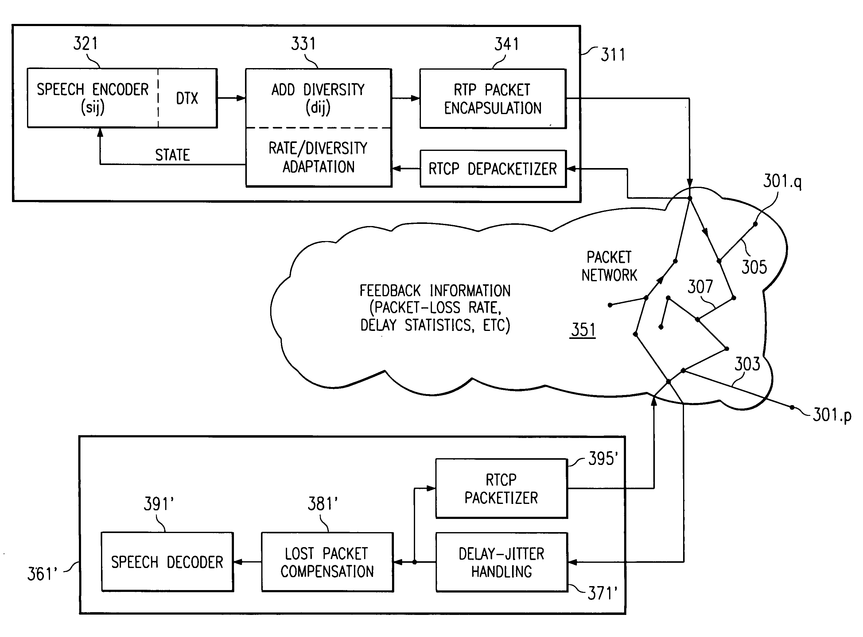
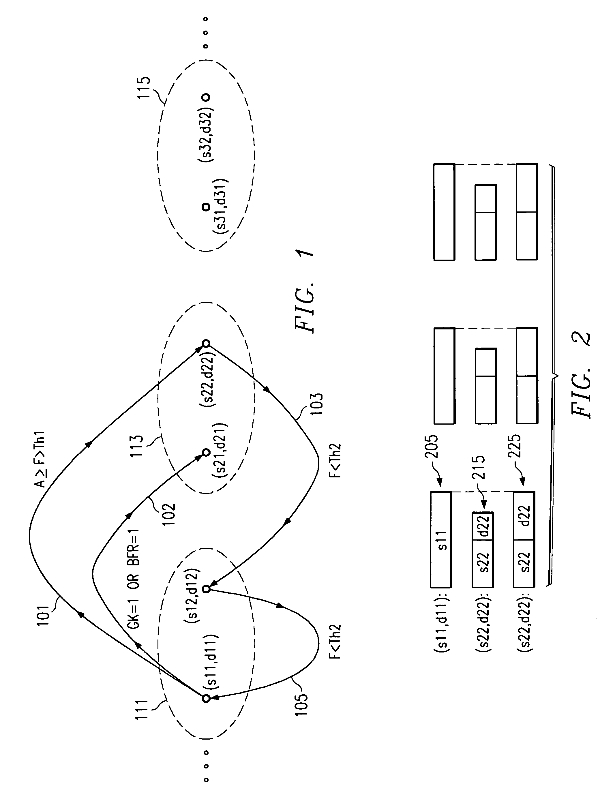
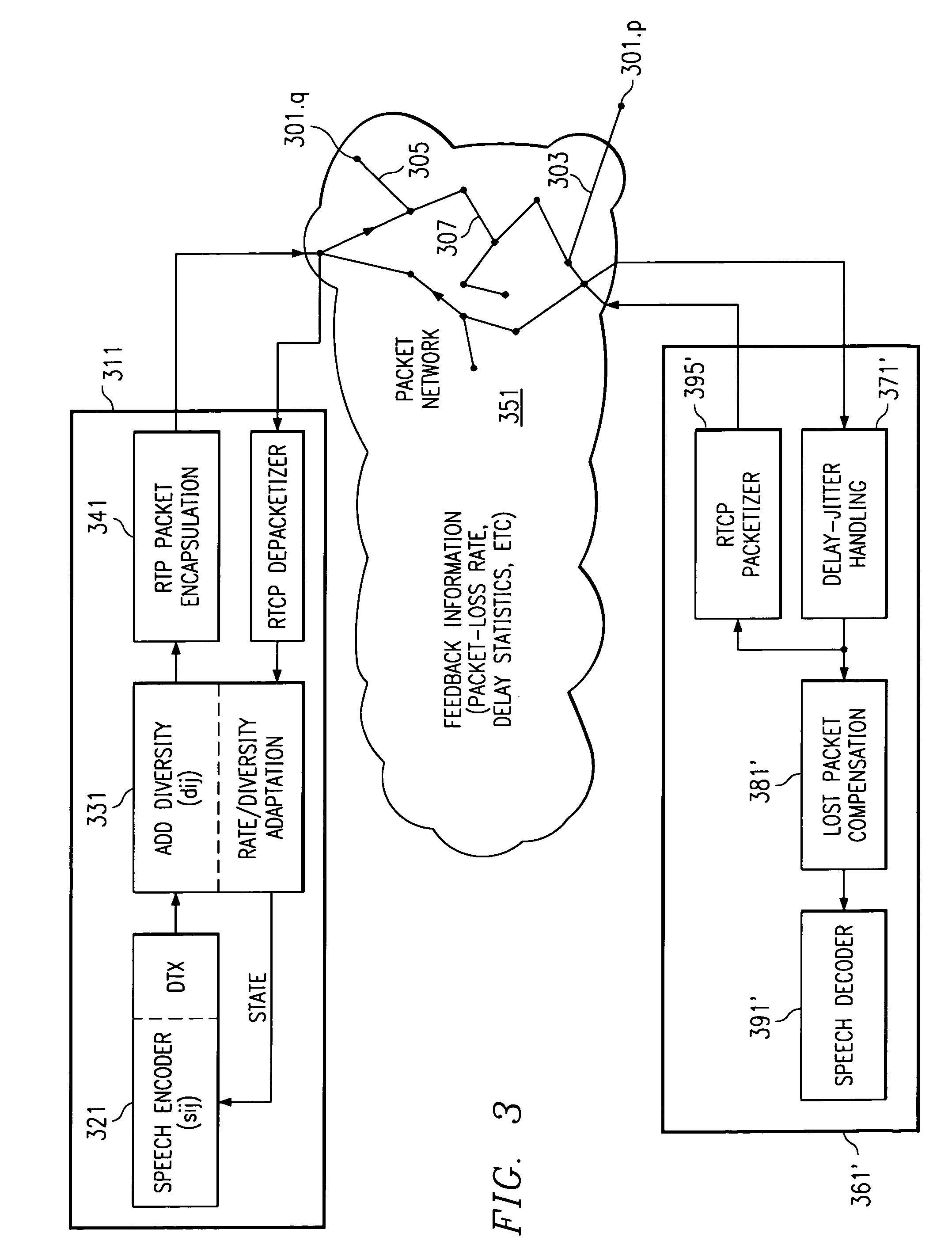
Packets of real-time information are sent with a source rate greater than zero kilobits per second, and a time or path or combined time/path diversity rate initially being zero kilobits per second. This results in a quality of service QoS, optionally measured at the sender or the receiver. When the QoS is on an unacceptable side of a threshold of acceptability, the sender sends diversity packets at an increased rate. Increasing the diversity rate while either reducing or maintaining the overall transmission rate is new. CELP-based multiple-description data partitioning sends the base or important information plus a subset of fixed excitation in one packet and sends the base or important information plus the complementary subset of fixed excitation in another packet. Reconstruction produces acceptable quality when only one of the two packets is received and better quality when both packets are received. Reconstruction provides for single and multiple lost packets.

Description


Claims


Application Information

Patent Timeline
Owner TEXAS INSTR INC
Learn More