Electrical connector

a technology of electrical connectors and connectors, applied in the direction of electrical equipment, live contact access prevention, coupling device connections, etc., to achieve the effect of facilitating mass production and saving working hours

Active Publication Date: 2009-08-18
LOTES
View PDF14 Cites 21 Cited by
  • Summary
  • Abstract
  • Description
  • Claims
  • Application Information

AI Technical Summary

Benefits of technology

[0006]The object of the present invention is to provide an electrical connector on which a cover plate is provided. During assembly, the cover plate can be fi

Problems solved by technology

Further, the cover plate may not suffer damage easily, the

Method used


Image

  • Electrical connector
  • Electrical connector
  • Electrical connector

Examples


Embodiment Construction

[0016]The electrical connector of the present invention will be further described with reference to preferred embodiments thereof in conjunction with the accompanying drawings.

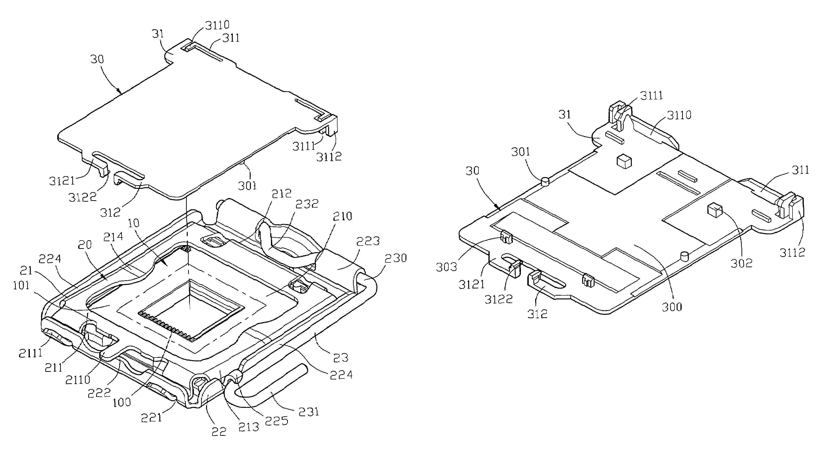
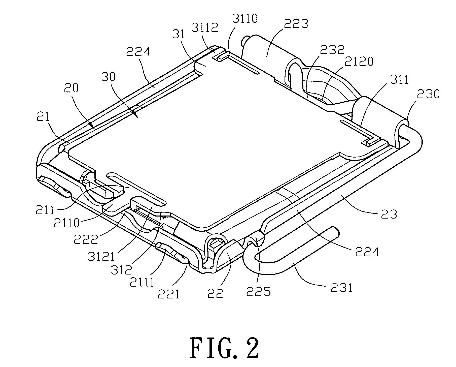
[0017]Please refer to FIG. 2 and FIG. 3. The present invention provides an electrical connector, which includes a connecting base 10, a fastener 20 and a cover plate 30. The connecting base 10 includes an insulating body 101 and a plurality of conductive terminals 100 received in the insulating body 101. The connecting base 10 is used to electrically connect a chip module (not shown) to a circuit board (not shown). The fastener 20 is located outside the connecting base 10. The cover 30 is used to cover the fastener 20.

[0018]Please refer to FIG. 3 and FIG. 5. The fastener 20 of the electrical connector of the present invention includes a lower cover 22, an upper cover 21 pivotingly connected with the lower cover 22, and a lever 23 for holding the upper cover 21 and the lower cover 22 together.

[0019]The middle p...


PUM


Abstract

An electrical connector includes: a fastener having an upper cover, a lower cover and a lever, the upper cover having a first side and a second side opposite to each other, the first side extending to form two pivoting ends pivotingly connected to the lower cover, the second side extending to form a clipping portion, the lever pressing the clipping portion, the lever being pivotingly connected with the lower cover; a cover plate covering the upper cover, both ends of one side of the cover plate being provided with a protruding portion respectively on which a first positioning portion is provided for engaging with the second side of the upper cover, the other side of the cover plate being provided with a set of second positioning portions for engaging with the first side of the upper cover. Thus the production yield is increased, and it is suitable for mass production.

Description

BACKGROUND OF THE INVENTION[0001]1. Field of the Invention[0002]The present invention relates to an electrical connector on which a cover plate is provided, whereby vacuum equipment can be used to transport the connector during manufacture.[0003]2. Description of Related Art[0004]With the mechanized manufacture in electronic elements, the vacuum suction technology is widely used in the mechanically mounting process of various electronic elements. In such a process, at first, a cover plate is fixed on an electronic element, and then a vacuum suction device suck a top surface of the cover plate. When adhesion of the vacuum suction device to the cover plate is achieved, the electronic element will follow the movements of the vacuum suction device and thereby be brought to a predetermined position on a circuit board. Finally, the electronic element is welded to the predetermined position of the circuit board. Please refer to FIG. 1, which is a schematic view showing a cover plate 10a an...

Claims


Application Information

Patent Timeline
IPC IPC(8): H01R13/44
CPCH05K7/1053Y10S439/94
Inventor CAI, CHAOWEN
Owner LOTES
Why Eureka
Try Eureka