
Above knee shrinker

a shrinker and knee technology, applied in the field of lower leg amputee textile products, to achieve the effect of providing compression, facilitating donation, and facilitating wear

Active Publication Date: 2009-08-18
KNIT RITE
View PDF21 Cites 13 Cited by
  • Summary
  • Abstract
  • Description
  • Claims
  • Application Information

AI Technical Summary

Benefits of technology

[0007]Responsive to these and other problems caused by conventional shrinkers, the present invention concerns an improved above knee shrinker for applying therapeutic compression to the residual limb of a lower-leg amputee. The invention provided hereof, among other things, is useful for providing more comfort to the wearer during use and donning, easier to don than conventional above knee shrinkers, and particularly effective in providing the desired compression.
[0008]A first aspect of the present invention concerns an above knee shrinker comprising a waist belt dimensioned for snugly receiving the waist of the wearer, and a tubular fabric receptacle dimensioned and configured to be worn on and apply a compressive force to the residual limb. The receptacle presents top and bottom ends, and is open adjacent each of the ends so that the residual limb can be inserted into the receptacle adjacent the top end. The receptacle is coupled to the waist belt adjacent the top end so that snug securement of the waist belt about the wearer's waist restricts vertical displacement of the receptacle along the residual limb. The receptacle is dimensioned so as to be longer than the residual limb, thereby permitting the receptacle to be doubled over the residual limb. The receptacle also includes a U-shaped edge projecting from the top end that presents a U-shaped perineal opening adjacent the torso end of the residual limb. Finally, the U-shaped edge includes a pair of spaced apart upright sections extending from the top end and a bottom section that is spaced from the top end and interconnects the upright sections.
[0009]A second aspect of the present invention concerns an above knee shrinker comprising a waist belt dimensioned for snugly receiving the waist of the wearer, and a tubular fabric receptacle dimensioned and configured to be worn on and apply a compressive force to the residual limb. The receptacle presents top and bottom ends, and is open adjacent each of the ends so that the residual limb can be inserted into the receptacle adjacent the top end. The receptacle is coupled to the waist belt adjacent the top end so that snug securement of the waist belt about the wearer's waist restricts vertical displacement of the receptacle along the residual limb. The receptacle is dimensioned so as to be longer than the residual limb, thereby permitting the receptacle to be doubled over the residual limb. Finally, the receptacle is knitted at least principally of core-spun yarn and includes a plurality of laid in elastic threads.

Problems solved by technology

These shrinkers, however, present various problems and disadvantages.
For example, the addition of belts has sacrificed comfort for stability by intruding the receptacle upon the amputee's perineal region.
Yet another problem is presented by the lack of lengthwise adjustability in conventional receptacles, which necessitates more shrinker sizes, and causes discomfort during donning.

Method used


Image

  • Above knee shrinker
  • Above knee shrinker
  • Above knee shrinker

Examples


Embodiment Construction

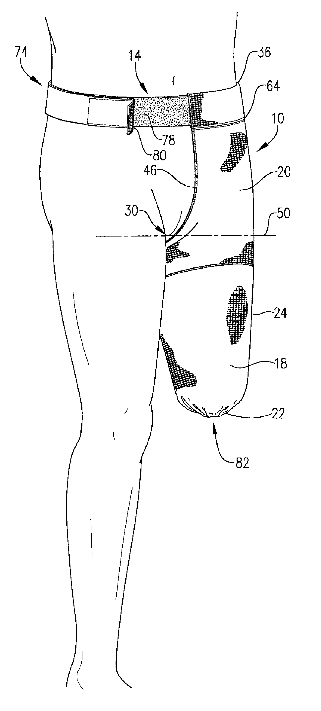
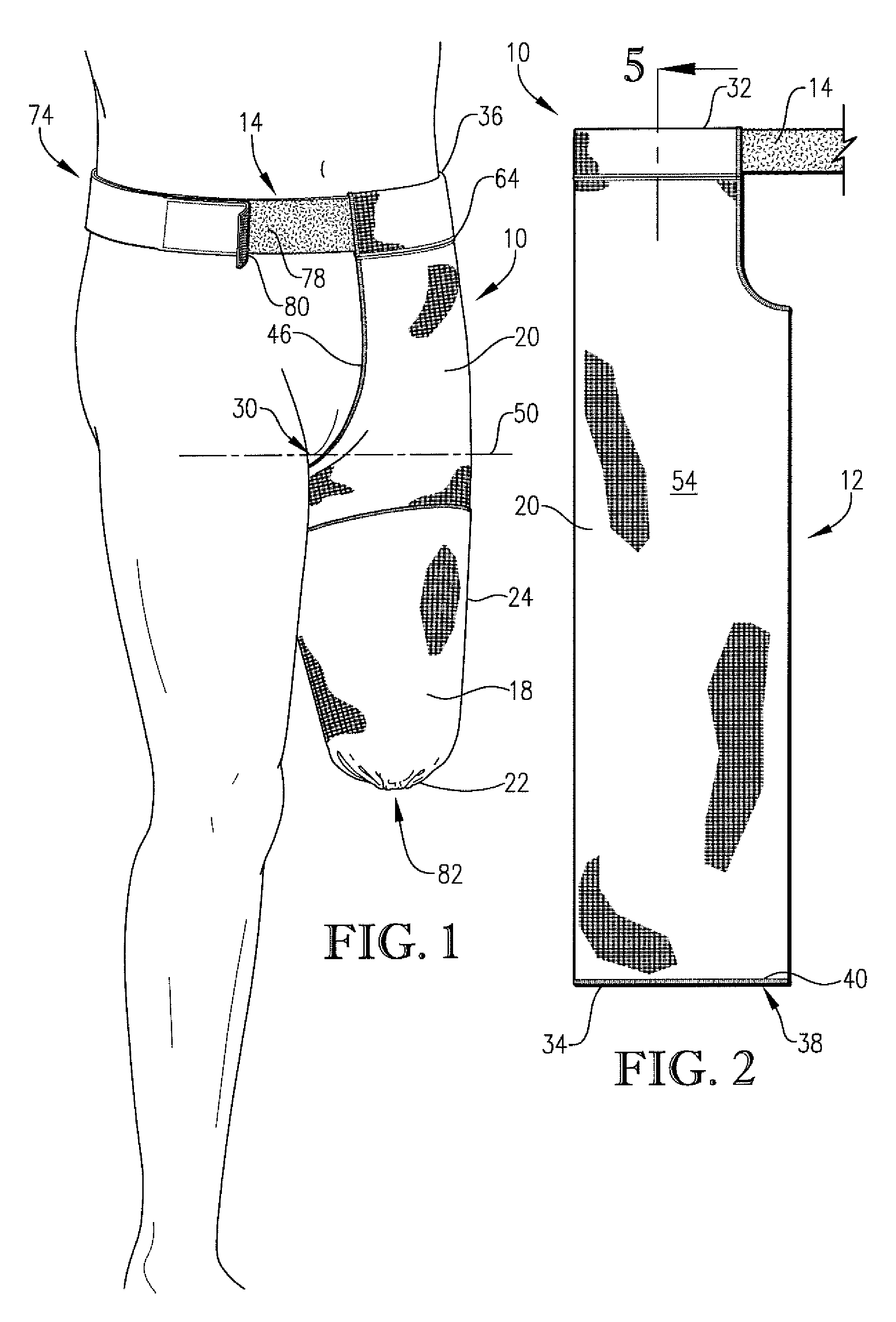
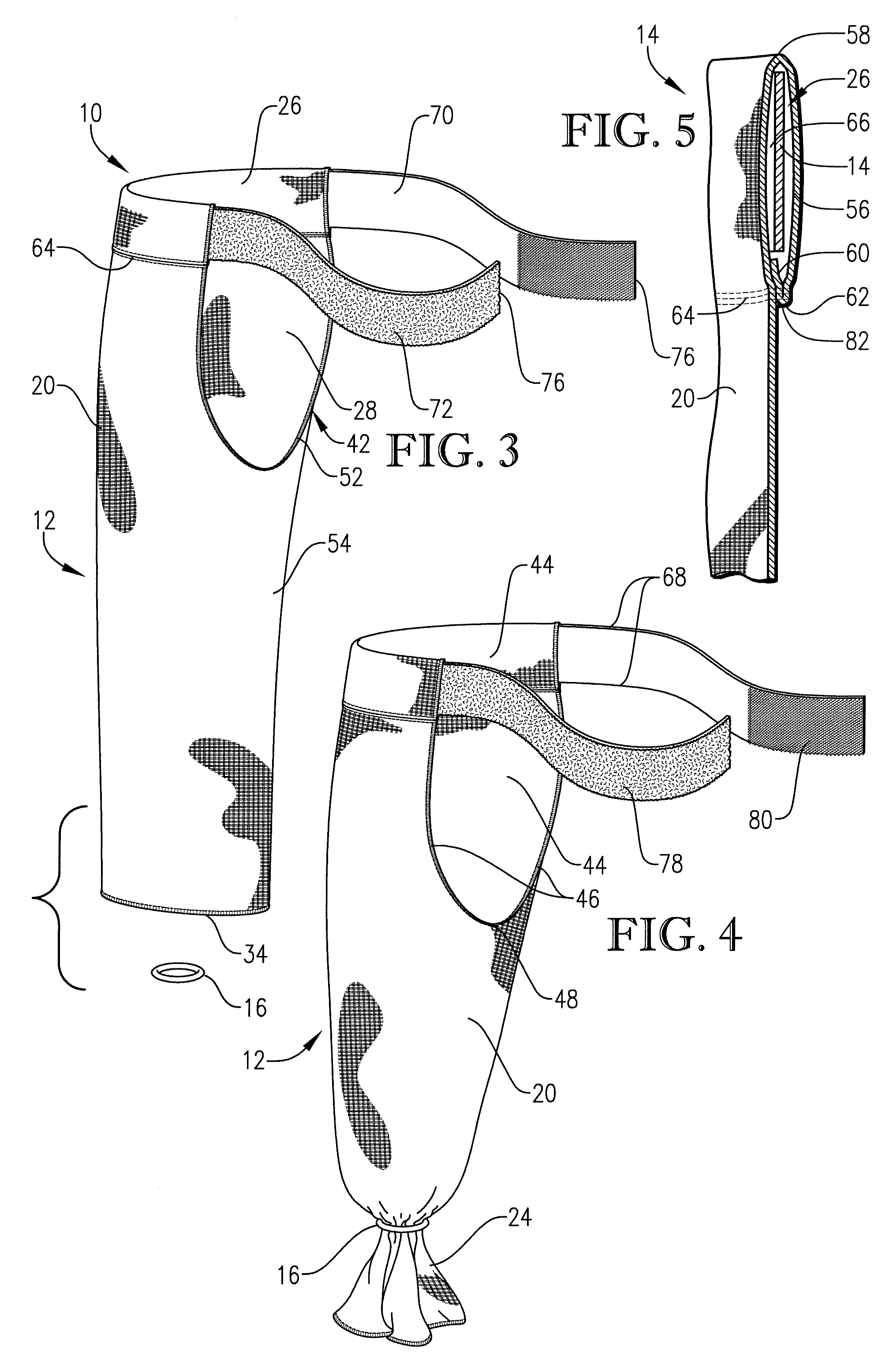
[0018]The above knee shrinker 10, selected for illustration in FIGS. 1-5, generally comprises a multi-directional stretch tubular fabric receptacle 12, a waist belt 14, and a constricting element 16. The shrinker 10 is operable to encircle and enclose the residual limb 18 of a lower-leg human amputee in a vertically secure position, and is suitably formed so as to apply a therapeutic compressive force to the residual limb 18. It is appreciated by those skilled in the art that the application of compressive force to the residual limb 18 reduces the risk of edema.

[0019]As best shown in FIG. 1, the receptacle 12 forms the primary component of the shrinker 10 and receives the residual limb 18. The receptacle 12 is dimensioned to conform to the contours of the residual limb 18 and provide an overhanging portion 24 that extends beyond the distal end 22 of the residual limb 18. The receptacle 12 presents a U-shaped perineal opening 28 to prevent uneven contact between the receptacle 12 and...


PUM


Abstract

An above knee shrinker includes a tubular fabric receptacle that encloses and applies therapeutic compression to the residual limb of a human trans-femoral lower-leg amputee. The shrinker includes a constricting element, and a moveably coupled waist belt. The receptacle is configured to present an overhanging portion that extends below the distal end of the residual limb and is able to be doubled-over at least a portion of the residual limb to apply additional compression thereto. The receptacle is configured to provide an improved U-shaped perineal opening. The receptacle is formed of a latex-free core spun yarn and spandex material that is comfortably stretchable in at least first and second substantially transverse directions. The waist belt presents an adjustable self-fastening mechanism, and the constricting element presents a sliding-ring that receives the overhanging portion and constricts the receptacle adjacent the distal end of the residual limb.

Description

BACKGROUND OF INVENTION[0001]1. Field of the Invention[0002]The present invention relates generally to manufactured textile products for lower-leg amputees. More specifically, the present invention concerns an above knee shrinker designed to comfortably apply therapeutic compression to the residual limb or stump of a lower-leg amputee.[0003]2. Discussion of Prior Art[0004]Compressive above knee shrinkers have been developed to post-operatively provide therapeutic compression to the residual limb of lower-leg or transfemoral amputee patients. The therapeutic compressive force applied by these shrinkers have been used to control and maintain stable soft tissue fluid volume, to reduce operative edema in the residual limb, and if worn nightly, to facilitate the fitting of a prosthesis the next morning. Conventional above knee shrinkers have incorporated waist belts and typically present tapered receptacles that extend to the belts, in an effort to vertically secure the shrinkers and, th...

Claims


Application Information

Patent Timeline
Patent Type & Authority Patents(United States)
IPC IPC(8): A61F13/00A61F2/80A61F13/06
CPCA61F13/06D10B2509/028D04B1/22
Inventor SMITH, MARK W. L.DALBEY, JEFFREY C.LANIER, JR., FREDERICK B.
Owner KNIT RITE
Learn More