Adaptive transmission timing control method, wireless communication system and wireless communication device

a transmission timing control and wireless communication technology, applied in the direction of synchronisation signal speed/phase control, synchronisation arrangement, electrical equipment, etc., can solve the problems of transmission timing control breaking down, path being missed, base path falling outside the delay-profile calculation range, etc., to prevent overlooking the base path

Inactive Publication Date: 2009-08-18
NEC CORP
View PDF3 Cites 44 Cited by
  • Summary
  • Abstract
  • Description
  • Claims
  • Application Information

AI Technical Summary

Benefits of technology

[0025]In accordance with the present invention, in a method for adaptive transmission timing control, by setting an upper limit for the transmission timing offset amount, which determines the change in a single iteration, and by offsetting the delay-profile calculation range in a follow-up of the change in transmission timing, an effect can be obtained of preventing overlooking of the base path on the base station side even in the event of having in the mobile station failed to demodulate the control information that contains the transmission timing offset amount.

Problems solved by technology

However, if on the side of the mobile station demodulation of the control information containing the transmission timing offset information fails, preventing the side of the mobile station from updating the transmission timing offset, the base path position remains unshifted so that, as shown in FIG. 13, solely the delay-profile calculation range at the base station is shifted, causing the base path to fall outside the delay-profile calculation range.
Consequently, the path is missed at the side of the base station, and the adaptive transmission timing control breaks down.

Method used


Image

  • Adaptive transmission timing control method, wireless communication system and wireless communication device
  • Adaptive transmission timing control method, wireless communication system and wireless communication device
  • Adaptive transmission timing control method, wireless communication system and wireless communication device

Examples


first embodiment

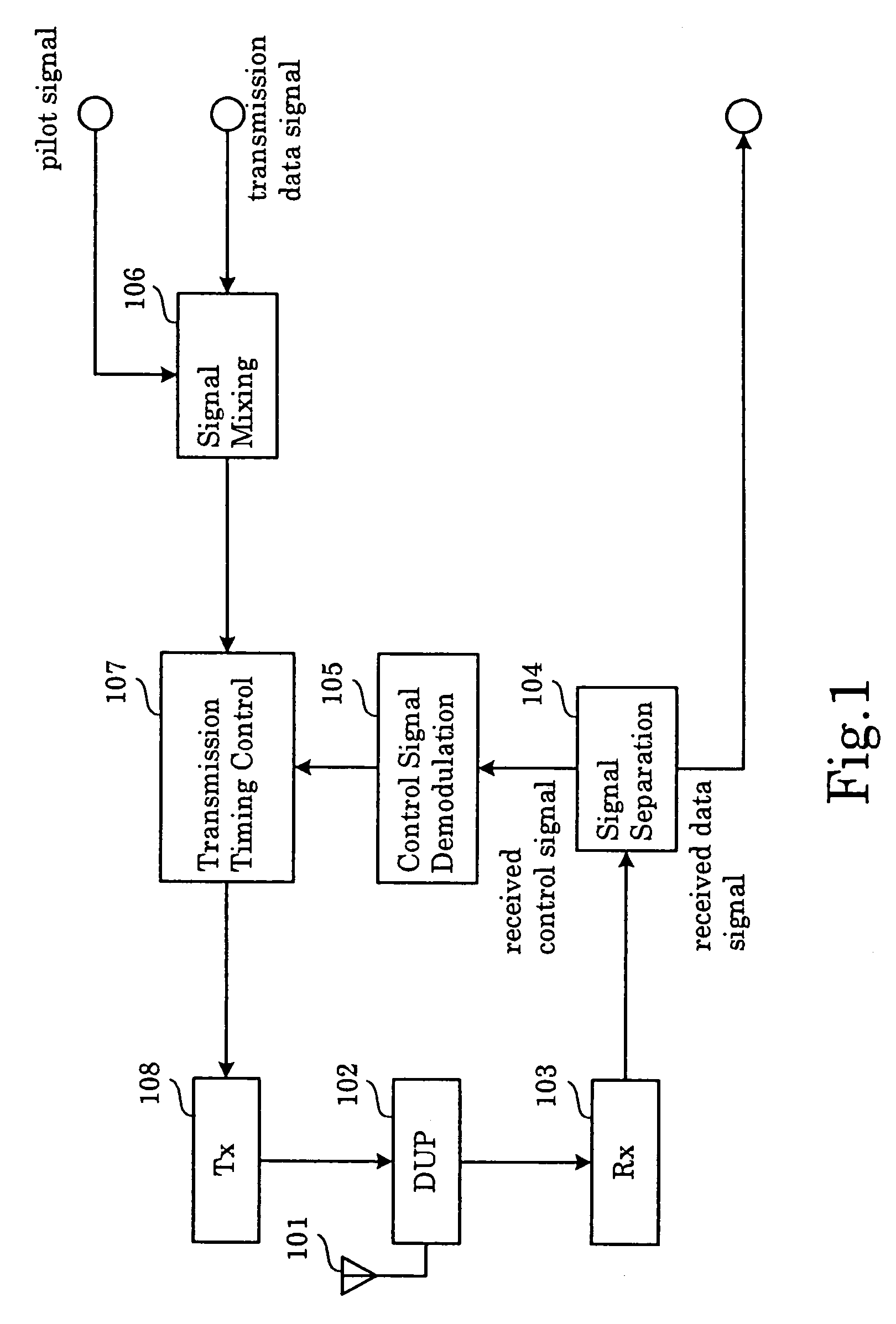
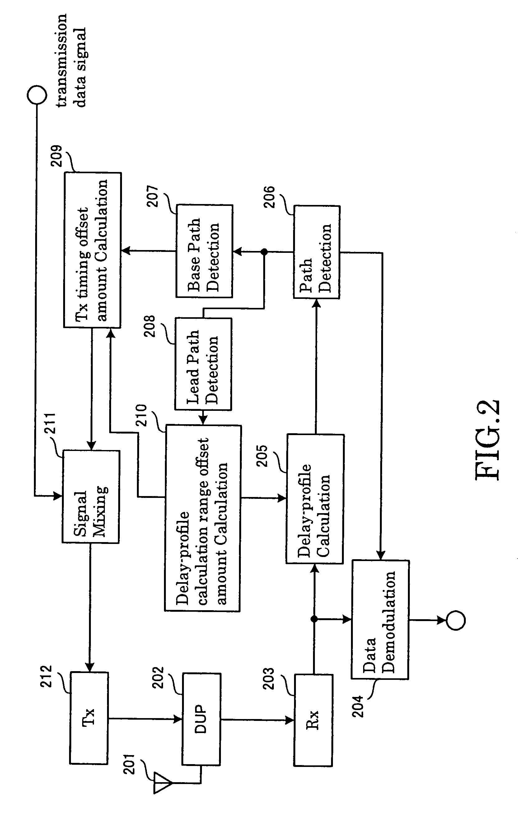
[0040]FIG. 1 and FIG. 2 are block diagrams showing the present invention, respectively showing configuration examples of a first wireless communication device and a second wireless communication device.

[0041]The first wireless communication device shown in FIG. 1 is constituted by antenna 101, transmission-reception duplexer (DUP: duplexer) 102, reception part 103, signal separation part 104, control signal demodulation part 105, signal mixing part 106, transmission timing control part 107, and transmission part 108.

[0042]Reception part 103, having received a signal from the second wireless communication device via antenna 101 and transmission-reception duplexer 102, sends this signal to signal separation part 104. Signal separation part 104 separates a data signal and a control signal, and sends the control signal to control signal demodulation part 105. Control signal demodulation part 105 demodulates the control signal and sends a transmission timing offset amount contained in th...

second embodiment

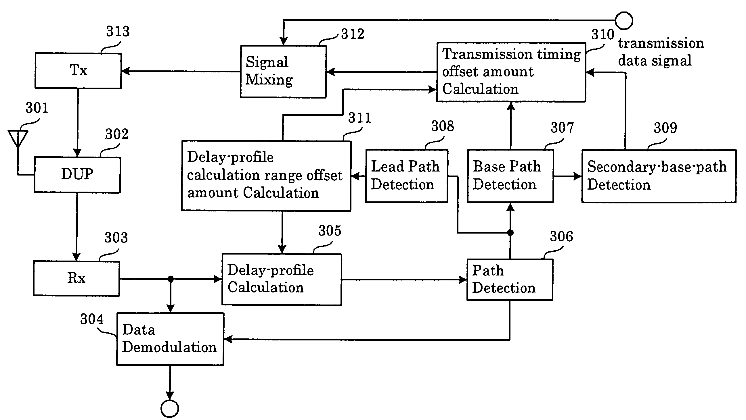
[0055]In the second embodiment, in addition to the base path also secondary base paths close to the base path in level and timing fall within the delay-profile calculation range, leading to an improvement of the error rate.


PUM


Abstract

In a method for adaptive transmission timing control, the overlooking of a base path at the side of the base station that occurs when the transmission timing offset amount changes to the extent of falling outside the current delay-profile calculation range, and the side of the mobile station fails to demodulate the control information that contains the transmission timing offset amount, is prevented. A limit is put on the transmission timing offset amount applied in a single transmission timing control iteration. Together with setting the transmission timing offset value such that the main component of the delay profile calculated from the pilot signal transmitted with offset transmission timing falls within the time range of when the current delay profile was calculated, the time range for calculating the next delay profile is shifted such that a delay profile calculated from the pilot signal transmitted with offset transmission timing falls within the shifted range, starting at the earliest component.

Description

BACKGROUND OF THE INVENTION[0001]1. Field of the Invention[0002]The present invention relates to wireless communication systems that perform transmission timing offset control.[0003]2. Description of Related Art[0004]With regard to wireless communications, it has been proposed to perform adaptive transmission timing control in order to support reception timing synchronization among mobile stations at the base station (see Technical Report of the Institute of Electronics, Information and Communication Engineers, RCS 2003-141). In a multiple-access scheme according to DS-CDMA (Direct Sequence—Code Division Multiple Access), by ensuring reception timing synchronization among mobile stations at the base station, the orthogonality of base paths among mobile stations concurrently accessing the base station can be ensured, allowing frequency utilization efficiency to be improved.[0005]The conventional adaptive transmission timing control is explained by making reference to FIGS. 9 to 11. F...

Claims


Application Information

Patent Timeline
Patent Type & Authority Patents(United States)
IPC IPC(8): H04J3/06H04B1/707H04B1/7117H04L7/08
CPCH04W56/0045H04W24/00
Inventor KIKUCHI, SHINGOMOCHIZUKI, TAKASHI
Owner NEC CORP
Why Eureka
Try Eureka