Wear assembly

a technology of wear and assembly, applied in the direction of soil shifting machines/dredgers, constructions, etc., can solve the problems of heavy load, harsh conditions for wear members of excavating equipment, etc., and achieve the effects of reducing storage needs, reducing shipping costs, and increasing coupling strength

Inactive Publication Date: 2009-08-25
ESCO GRP LLC
View PDF48 Cites 55 Cited by
  • Summary
  • Abstract
  • Description
  • Claims
  • Application Information

AI Technical Summary

Benefits of technology

[0004]The present invention pertains to an improved wear assembly for excavating equipment, wherein the wear member is secured by a locking arrangement having improved stability, strength, durability, safety, and ease of use.
[0005]In accordance with one aspect of the invention, the wear member has an opening with angled bearing surfaces to bear against an inserted lock for increased stability and strength, and reduced wear. In one embodiment, the bearing surfaces are inclined forward and away from the longitudinal axis in opposite lateral directions to bear against complementary surfaces in the lock.
[0006]In accordance with another aspect of the invention, the wear member has a tapering opening that defines an expanded bearing area and a narrowed anchoring area for the lock. In this construction, the wear member and the lock contact over a large surface area to transfer the applied loads while providing easy manipulation of the lock and minimizing of the overall opening size.

Problems solved by technology

Wear members for excavating equipment are commonly subjected to harsh conditions and heavy loading.

Method used


Image

  • Wear assembly
  • Wear assembly
  • Wear assembly

Examples


Embodiment Construction

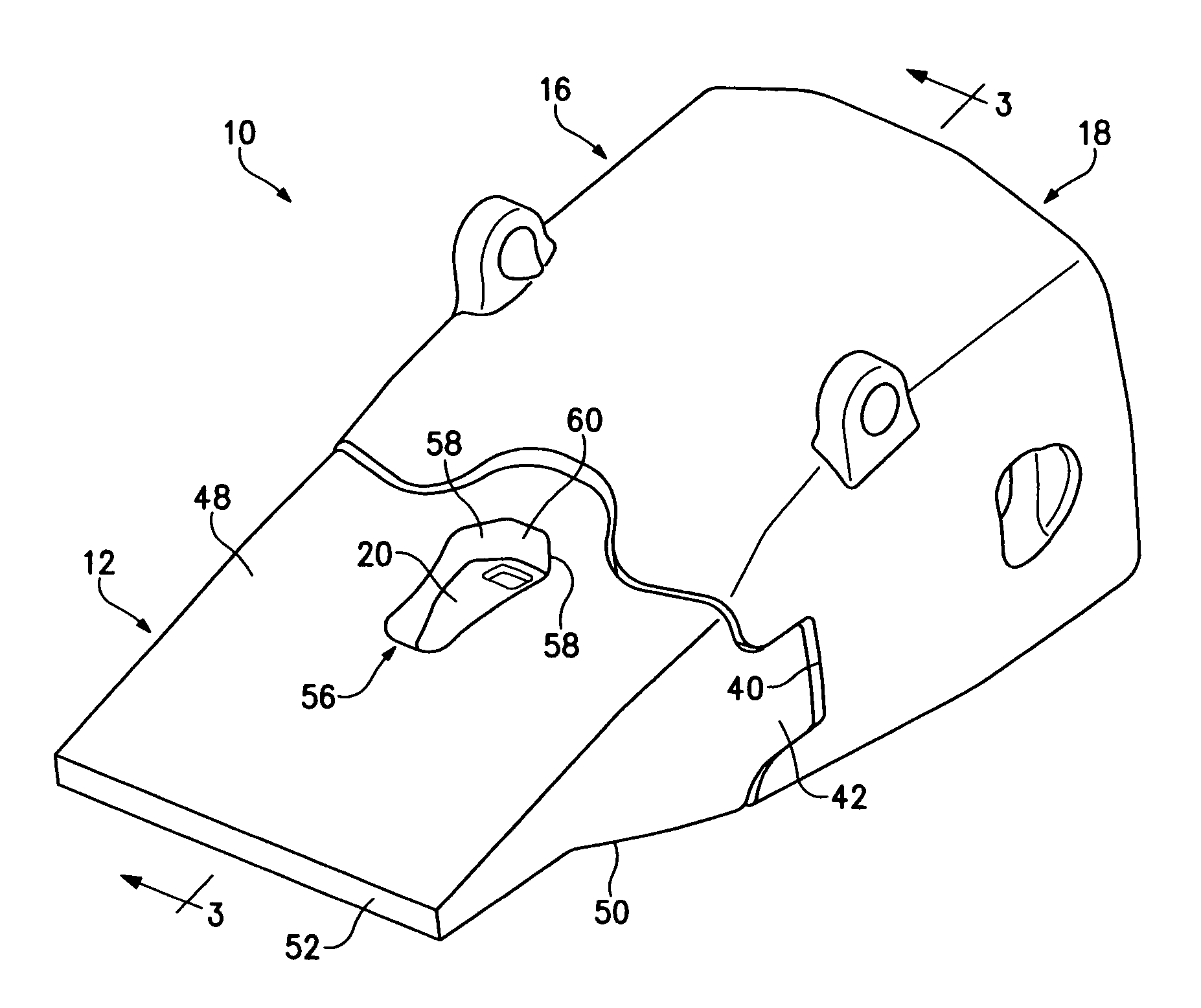
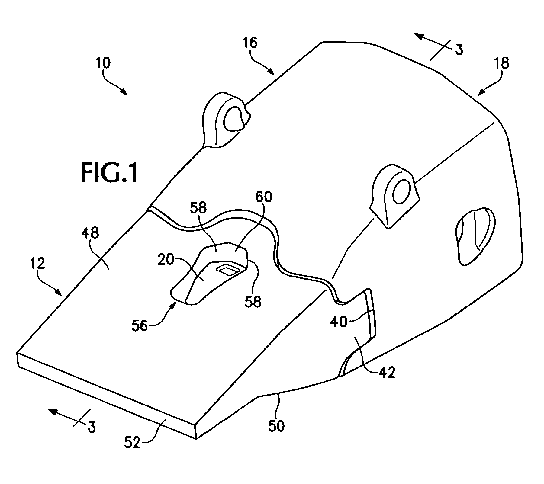
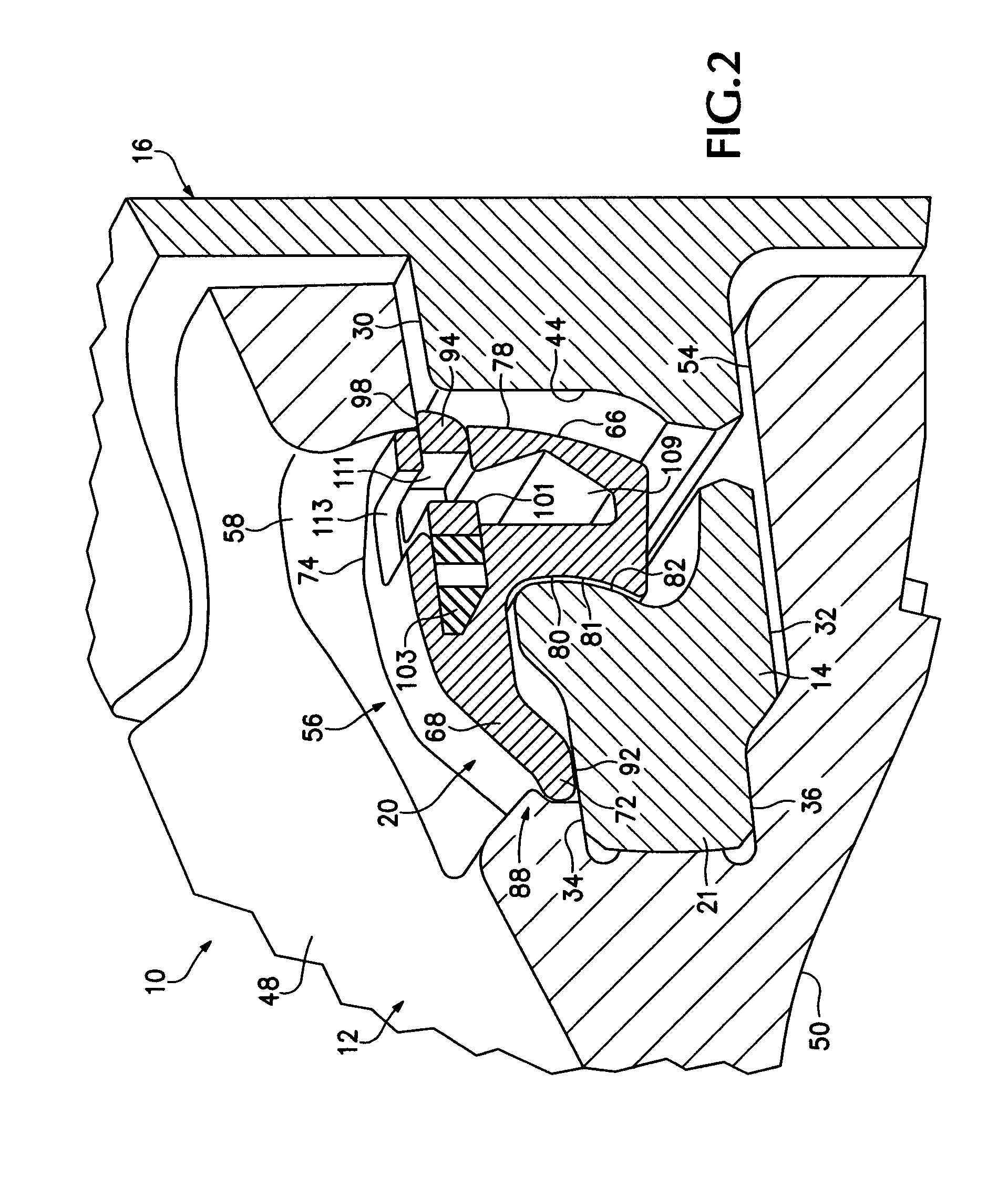
[0050]The present invention pertains to a wear assembly 10 (FIG. 1) for releasably attaching a wear member 12 to excavating equipment (not shown). In this application, wear member 12 is described in terms of a point or tip for an excavating tooth that is attached to a lip of an excavating bucket. However, the wear member could be in the form of other kinds of wear parts (e.g., shrouds) or attached to other excavating equipment (e.g., dredge cutterheads). Moreover, relative terms such as forward, rearward, vertical, horizontal up or down are used for convenience of explanation with reference to FIG. 1; other orientations are possible.

[0051]In one embodiment, the wear member or point 12 is adapted to fit on a nose 14 (FIG. 14) of a base member 16, which in this example, is an adapter. Adapter 16 is a medial adapter which includes a rearwardly opening socket 18 to fit onto a nose of a second base (not shown). This second base is fixed to the digging edge of the bucket by welding, mecha...


PUM


Abstract

A wear assembly for excavating equipment that includes a base, a wear part and an improved locking arrangement that provides improved stability, strength, durability, safety and ease of use. The locking arrangement includes a hammerless lock that is pivotally moved between hold and release positions, wherein the fulcrum is set forward of the bearing surface engaging the wear part. The lock can be manipulated by a threaded member or pry tool. The lock further includes bearing surfaces that enhance stability and reduce wear.

Description

FIELD OF THE INVENTION[0001]The present invention pertains to a wear assembly for securing a wear member to excavating equipment.BACKGROUND OF THE INVENTION[0002]Wear parts are commonly attached along the lip of an excavating bucket or the digging edge of other excavating equipment (such as dredge cutterheads) to protect the equipment from wear and enhance the digging operation. The wear parts may be excavating teeth, shrouds, or other wear members. These assemblies typically include a base, a wear member, and a lock. The base is fixed to the digging edge, and the wear member fits over the base. The assembled base and wear member cooperatively define an opening into which the lock is received to releasably hold the wear member to the base.[0003]Wear members for excavating equipment are commonly subjected to harsh conditions and heavy loading. Accordingly, it is desirable for the locking arrangement to be strong to effectively retain the wear member to the equipment, and also easily ...

Claims


Application Information

Patent Timeline
Patent Type & Authority Patents(United States)
IPC IPC(8): E02F9/28
CPCE02F9/2841E02F9/2825
Inventor BEARDEN, JAMES EDURAND, SEVERN DSEVERSON, MICHAEL ACARPENTER, CHRISTOPHER M
Owner ESCO GRP LLC
Why Eureka
Try Eureka