Double bus bar load center

a load center and bus bar technology, applied in the direction of substation/switching arrangement casings, non-enclosed substations, substations, etc., can solve the problems of inflexible bus bar assembly, circuit breaker trip and interrupt power, and different size bus bar assembly

Active Publication Date: 2009-08-25
SQUARE D CO
View PDF16 Cites 22 Cited by
  • Summary
  • Abstract
  • Description
  • Claims
  • Application Information

AI Technical Summary

Problems solved by technology

Overload protection is provided by a thermal element which, when heated by the increased current, will cause the circuit breaker to trip and interrupt the power.
This can occur when too many loads draw power from the same branch circuit at the same time, or when a single load draws more power than the branch circuit is designed to carry.
One problem associated with some current load centers is that they include a bus bar assembly that fails to accommodate different sized circuit breakers.
For example, this type of bus bar assembly will only accept one-inch circuit breakers or only half-inch circuit breakers, but not both.
This type of bus bar assembly is inflexible and undesirable for numerous electrical applications.
Although some current bus bar assemblies try to address the above stated problem, this type of bus bar assemblies can be unreliable and can provide poor quality.
This type of connection, either using a braze or a mechanical stake, inherently may introduce a problem-prone design that increases the opportunity for faulty connections (e.g., poor joining technique or material).
Furthermore, this type of connection may fail over time due to stresses caused by normal use of circuit breakers (e.g., tripping the circuit breaker, replacing the circuit breaker, etc.).
Additionally, the use of brazing and / or mechanical stakes can increase manufacturing costs and time.

Method used


Image

  • Double bus bar load center
  • Double bus bar load center
  • Double bus bar load center

Examples


Embodiment Construction

[0021]Although the invention will be described in connection with certain preferred embodiments, it will be understood that the invention is not limited to those particular embodiments. On the contrary, the invention is intended to include all alternatives, modifications and equivalent arrangements as may be included within the spirit and scope of the invention as defined by the appended claims.

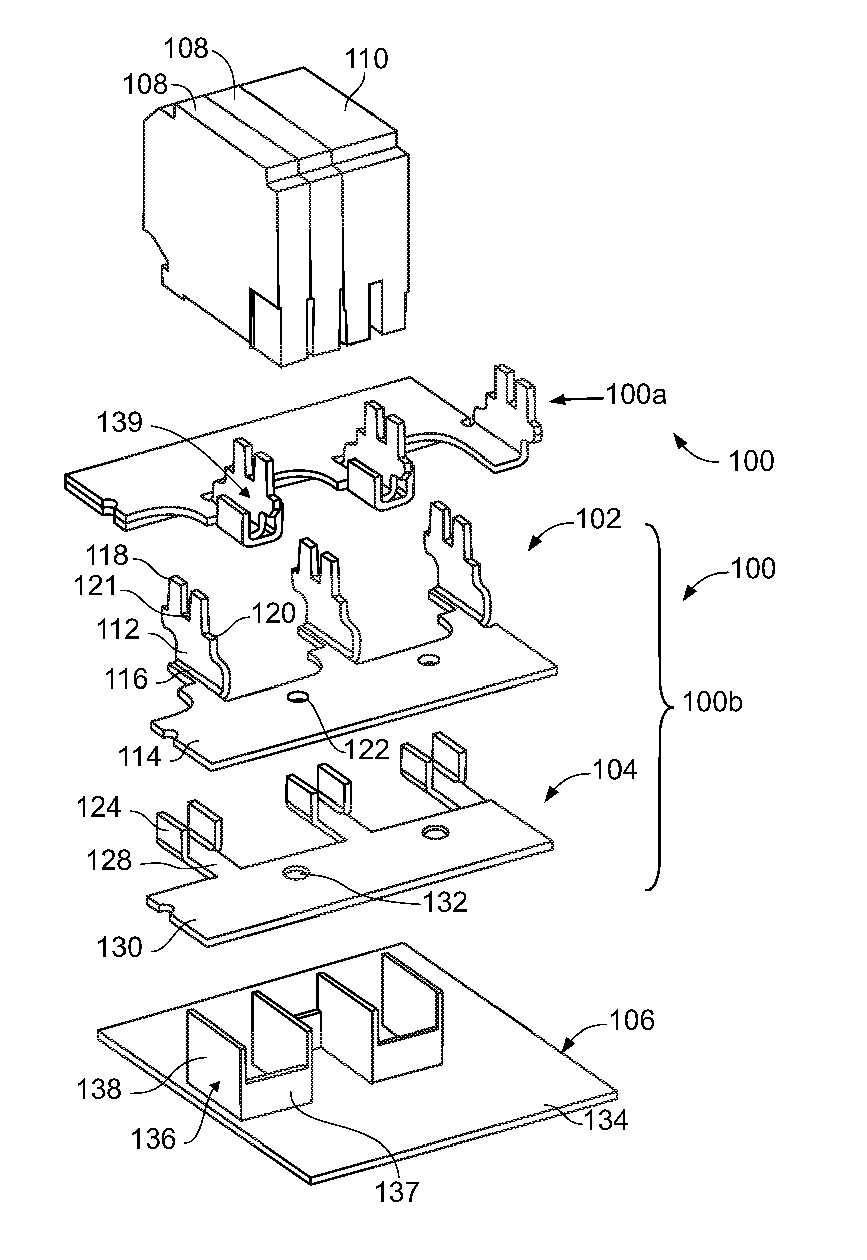
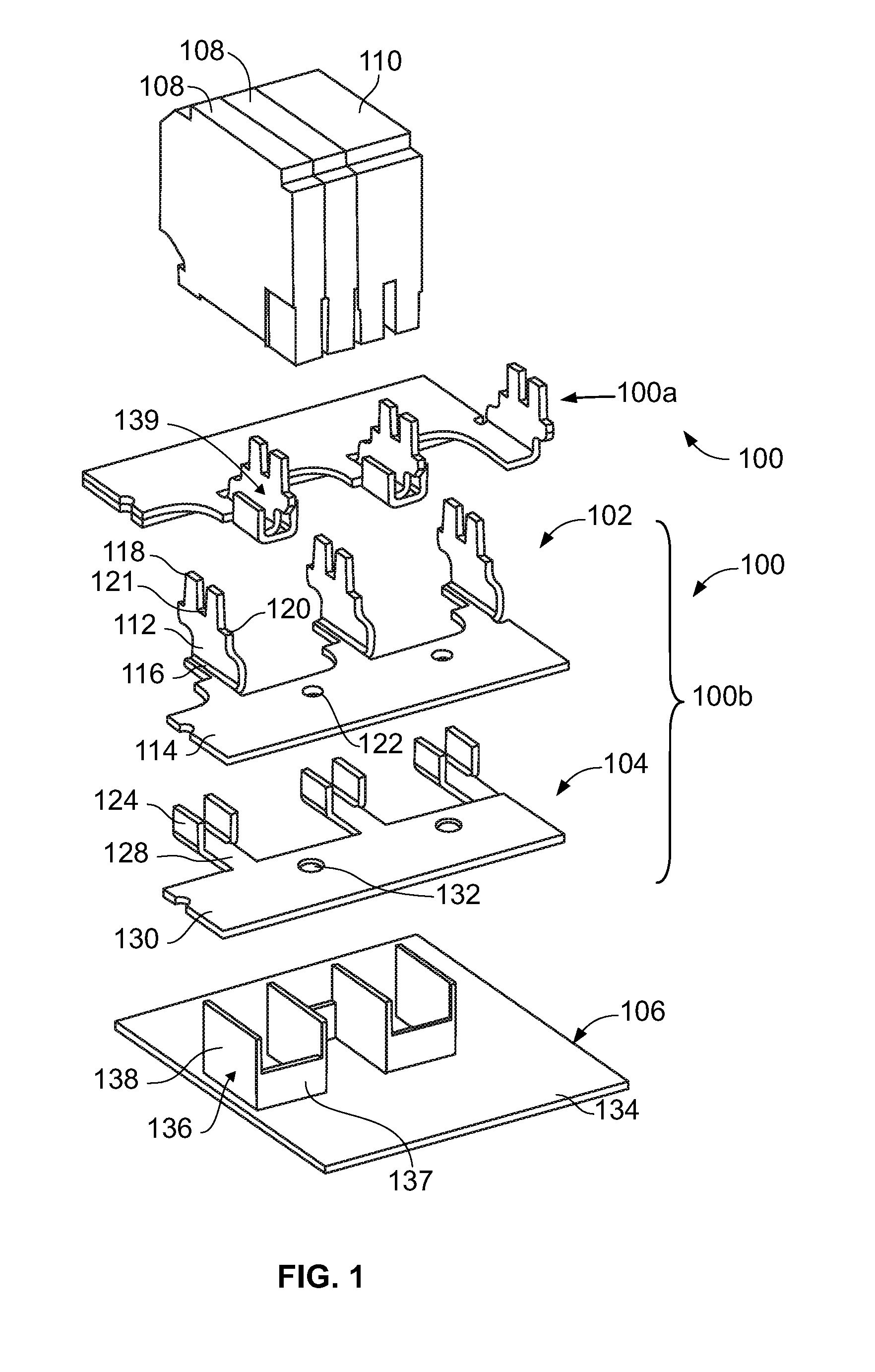
[0022]Referring to FIG. 1, two double bus bar assemblies collectively 100 (an assembled left double bus bar assembly 100a and an exploded right double bus bar assembly 100b) for an electrical load center include generally the same features, except that the double bus bar assemblies 100 are offset mirror images of each other and can be interwoven. As such, reference is made generally to features of only one of the double bus bar assemblies 100, with the understanding that the other one of the double bus bar assemblies 100 includes the same (symmetrically formed) features. According to an alter...


PUM


Abstract

A load center system includes a primary bus bar with primary stabs for receiving a first type of circuit breaker, the primary stab extending from a primary base portion of the primary bus bar. A secondary bus bar with a secondary base portion and secondary stabs is coupled to the primary bus bar in a generally overlapping position, for receiving a second type of circuit breaker. Both the primary and secondary bus bars can be formed from stamping. By utilizing bus bars with base portions, the primary and secondary bus bars together provide for ease of assembly, and structural integrity, while allowing either of the first type of circuit breaker and the second type of circuit breaker to be coupled to the load center.

Description

FIELD OF THE INVENTION[0001]This invention is directed generally to electrical load centers, and, more particularly, to a load center having a double bus bar for receiving circuit breakers of different sizes.BACKGROUND OF THE INVENTION[0002]Electrical systems in residential, commercial and industrial applications usually include a load center (also referred to as a panelboard) for receiving electrical power from a utility source. The power is connected to the load center via line bus bars and neutral bus bars. The electrical power is delivered from the load center to designated branch circuits through line and neutral conductors supplying one or more loads. Typically, various types of protective devices are mounted to the bus bars of the load center to protect the branch circuits from hazardous electrical conditions and reduce the risk of injury, damage or fires.[0003]Standard circuit breakers are one type of protective device for protecting the branch circuits from certain hazardou...

Claims


Application Information

Patent Timeline
Patent Type & Authority Patents(United States)
IPC IPC(8): H02B1/20H02B5/00
CPCH02B1/056
Inventor PEARSON, DAVEBROGHAMMER, WILLIAM J.
Owner SQUARE D CO
Why Eureka
Try Eureka