Comprehensive network monitoring at broadcast satellite sites located outside of the broadcast service area

a satellite site and satellite technology, applied in the field of network monitoring of broadcast signal transmission, can solve the problems of significant cost, uncertainty in the quality of monitoring, and channel being broadcast cannot be directly received at the service area,

Active Publication Date: 2009-08-25
DIRECTV LLC
View PDF25 Cites 11 Cited by
  • Summary
  • Abstract
  • Description
  • Claims
  • Application Information

AI Technical Summary

Benefits of technology

[0007]The present invention provides simplicity in that the same program content and management control signals (e.g., program guide signals, conditional access) are integrated into the service broadcasts and are used by the monitoring receivers to access desired channels. To monitor against problems in the transmission from the broadcast site to the service area, a transmission monitoring system at the service area provides signal strength readings to the network monitoring system using a low bandwidth return signal.

Problems solved by technology

When the broadcast system has one or more service areas that have locations that do not include the broadcast site, the channels being broadcast cannot be directly received at the service area.
However, this solution introduces significant cost as the broadcast signals typically have very high bandwidth.
Further, there is uncertainty in the quality of the monitoring because the transmission path returning the broadcast signals to the network monitoring function may themselves introduce degradations and outages that do not actually occur in the broadcast itself.
This is a huge cost burden.
Furthermore, the success rate in troubleshooting and resolving problems would most likely be lower due to the complexity of such a distributed organization.

Method used


Image

  • Comprehensive network monitoring at broadcast satellite sites located outside of the broadcast service area
  • Comprehensive network monitoring at broadcast satellite sites located outside of the broadcast service area
  • Comprehensive network monitoring at broadcast satellite sites located outside of the broadcast service area

Examples


Embodiment Construction

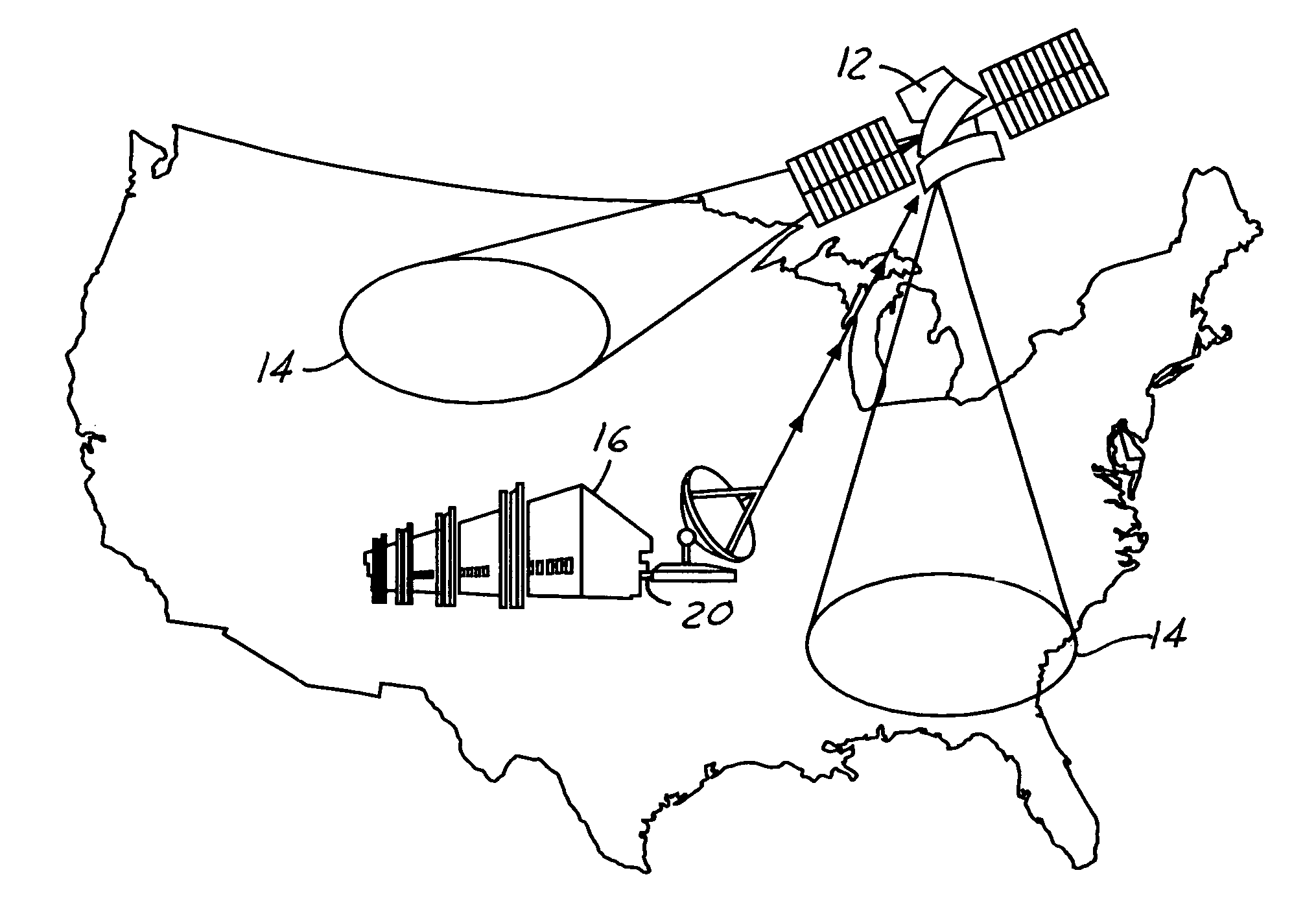
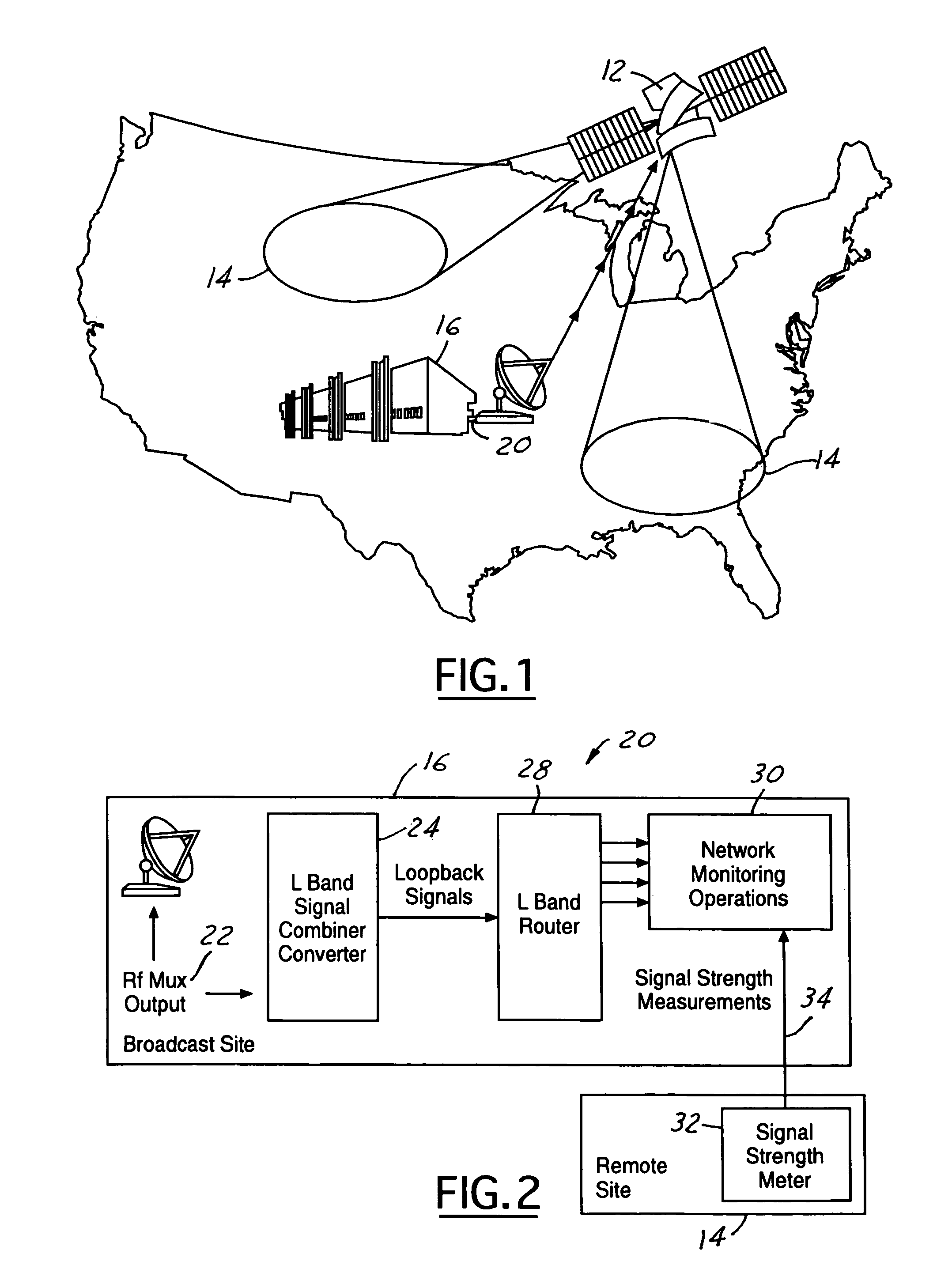
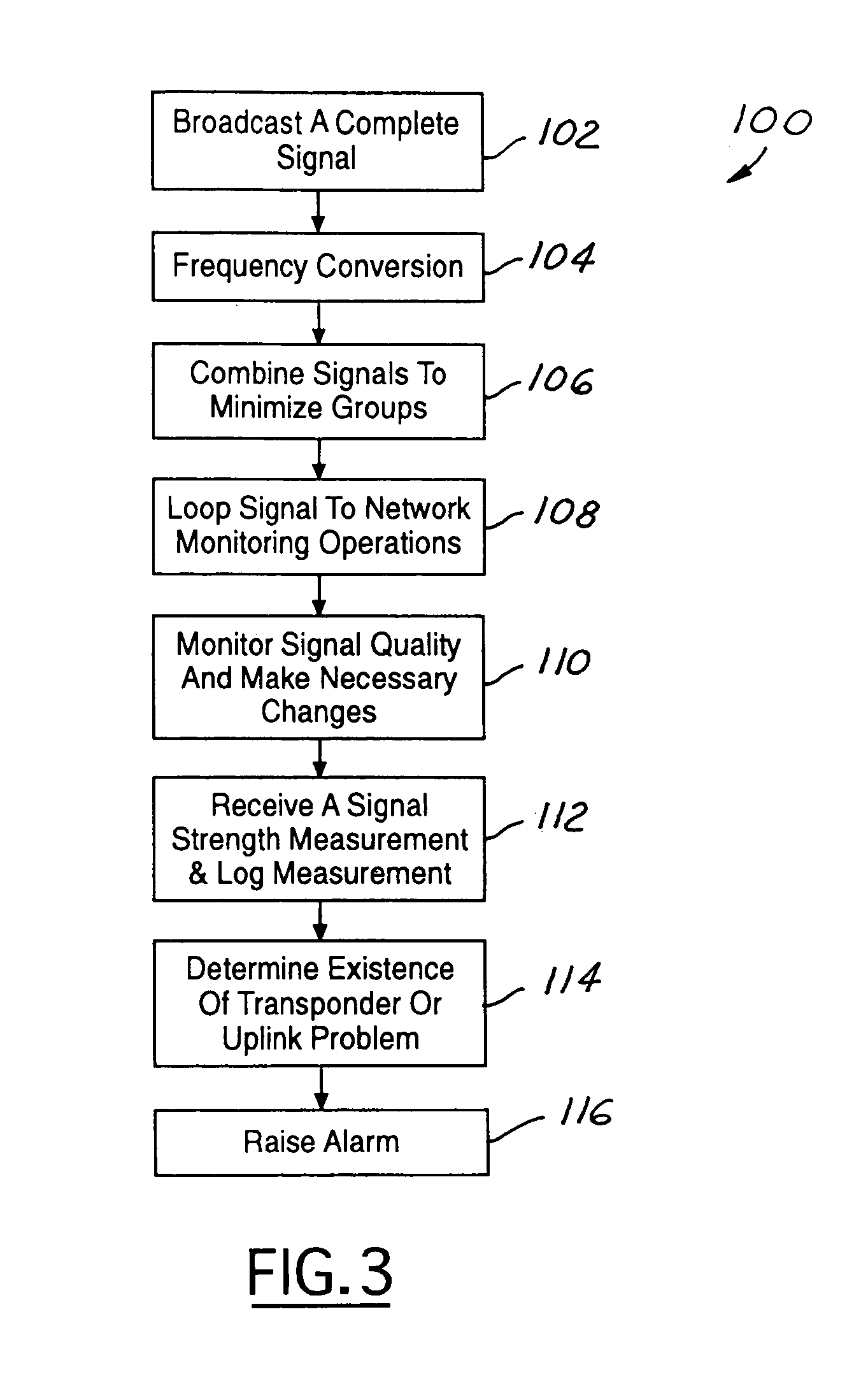
[0014]FIG. 1 is an example of a spot beam satellite network system 10. A satellite 12 services a plurality of service areas 14. A network monitoring center 16 broadcasts signals to the satellite 12. The satellite 12 redistributes the signals to the plurality of service areas 14 by way of spot beams where the signals for the specific area are received by the intended recipients, i.e. television signals for area subscribers.

[0015]The remote service areas are outside of the direct broadcast range of the centralized network monitoring center 16, making it impossible for the network monitoring center 16 to receive the signals being broadcast to the remote service areas 14. According to the present invention, the monitoring function 20 for the remote sites is done at the broadcast site 16 when the signal exits the network monitoring center. The verification of the transmission delivery to the service area is done at the remote site.

[0016]Referring now to FIG. 2 there is shown a block diag...


PUM


Abstract

A system and method for monitoring the quality of signals transmitted to a remote service area that is located outside of the broadcast area of a main broadcast site. The present invention converts and combines the signals that are to be broadcast from the main broadcast site to a satellite for redistribution to the remote service areas. The converted and combined signals are looped back to a network monitoring operations located at the main broadcast site before being transmitted to the satellite. In another embodiment, the remote broadcast sites send signal strength measurements to the network monitoring operations to provide an indication of satellite transmission problems not related to the quality of the signal being broadcast from the main broadcast site.

Description

RELATED APPLICATION[0001]The present application is a continuation of U.S. patent application Ser. No. 10 / 291,165 filed on Nov. 8, 2002, entitled “Comprehensive Network Monitoring At Broadcast Satellite Sites Located Outside Of The Broadcast Service Area”.TECHNICAL FIELD[0002]The present invention relates generally to network monitoring of a broadcast signal transmission and more particularly to comprehensive network monitoring of a broadcast signal transmission at broadcast sites located outside of a broadcast service area.BACKGROUND OF THE INVENTION[0003]It is essential that comprehensive network monitoring of the broadcast signal be maintained to provide early detection, troubleshooting and problem resolution. Typically there is an undiminished capability for monitoring a broadcast signal because the information and signals are readily available to the network operations functions as these operations are within the broadcast area. A single, central network monitoring function is ...

Claims


Application Information

Patent Timeline
Patent Type & Authority Patents(United States)
IPC IPC(8): H04W4/00H04N3/02H04B7/185H04B7/19H04H1/00H04H20/74H04L12/50H04N17/00
CPCH04B7/18523H04H20/02H04H20/14H04N17/00H04L12/2602H04L43/00H04H20/74
Inventor BARRETT, RONALD C.
Owner DIRECTV LLC
Why Eureka
Try Eureka