Hybrid dehumidification system for applications with high internally-generated moisture loads

a dehumidification system and high moisture load technology, applied in the direction of defrosting, heating types, domestic cooling apparatus, etc., can solve the problem of indoor humidity falling below the set point, and achieve the effect of reducing outside air and saving energy

Active Publication Date: 2009-09-01
KENTUCKIANA CURB
View PDF8 Cites 29 Cited by
  • Summary
  • Abstract
  • Description
  • Claims
  • Application Information

AI Technical Summary

Benefits of technology

[0004]It is therefore an object of the present invention to provide a dehumidification system which can be used in high moisture load environments.
[0005]It is also an object of the present invention to provide a hybrid dehumidification system which utilizes both mechanical and ventilation modes and which promotes modulated dehumidification of air in an enclosed space.
[0008]In the mechanical dehumidification mode, the required outside air and exhaust air for ventilation is furnished by a minimum outside air and minimum exhaust air damper that introduces the outside air necessary to ventilate the enclosed space and exhaust air sufficient to maintain negative pressure within the enclosed space as may be required by design or code and to avoid “pushing” humid air into adjacent spaces or into cold wall cavities where it can condense and cause damage. In the outdoor air dehumidification mode the ventilation is easily met except possibly at very low outdoor temperatures, in which case the outdoor air required to meet the ventilation requirement may cause the indoor humidity to fall below set point. An air bypass is also provided with regulating orifice in the event that additional airflow is needed to meet the total system airflow requirement. The invention has a purge feature that allows the system to operate with 100% outside air / 100% exhaust to purge the enclosed space of contaminants such as excessive chloramines in an indoor swimming pool environment.

Problems solved by technology

In the outdoor air dehumidification mode the ventilation is easily met except possibly at very low outdoor temperatures, in which case the outdoor air required to meet the ventilation requirement may cause the indoor humidity to fall below set point.

Method used


Image

  • Hybrid dehumidification system for applications with high internally-generated moisture loads
  • Hybrid dehumidification system for applications with high internally-generated moisture loads
  • Hybrid dehumidification system for applications with high internally-generated moisture loads

Examples


Embodiment Construction

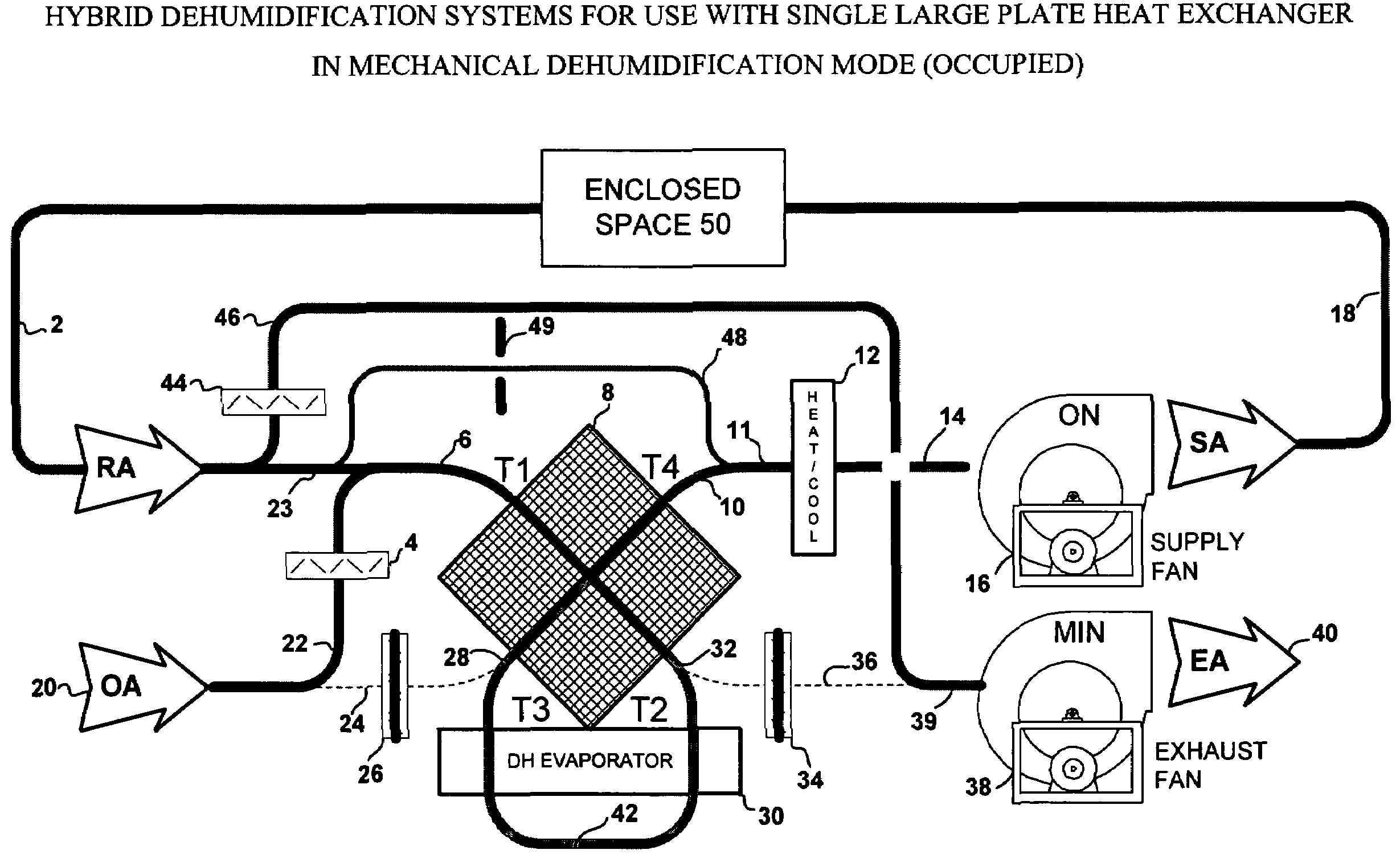
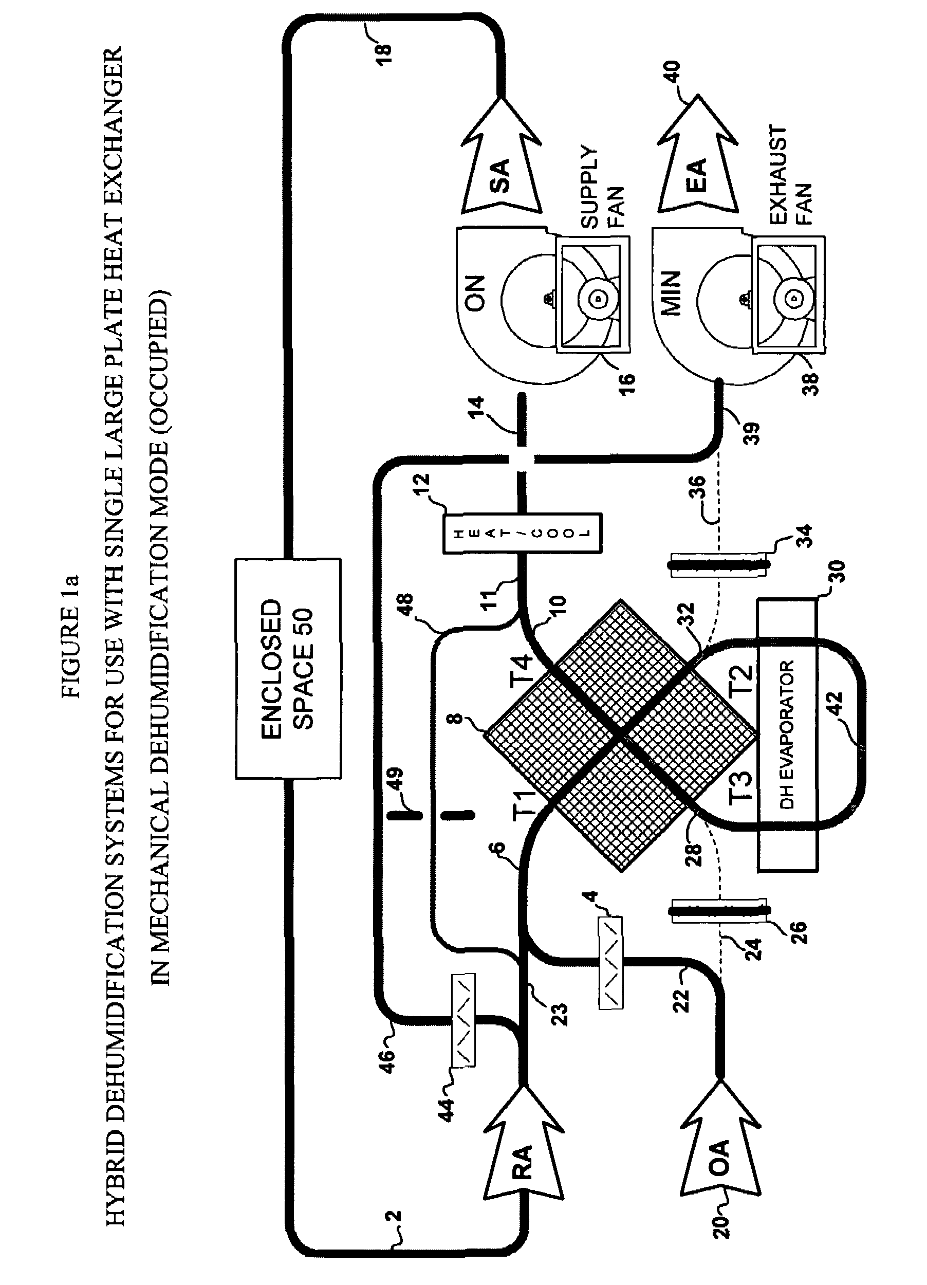
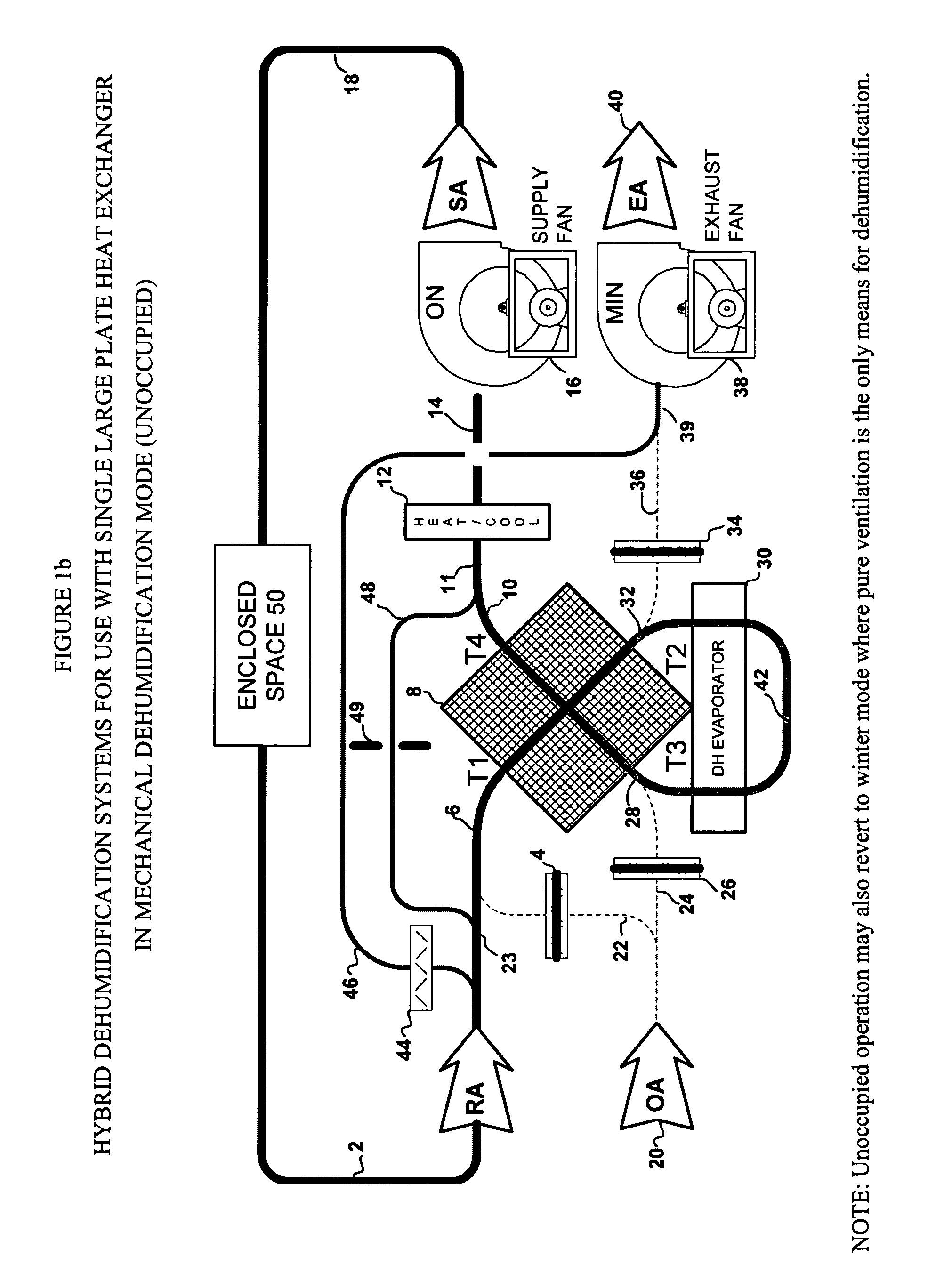
[0024]The invention uses at least one modulating outside air damper 26 and at least one modulating exhaust air damper 34 and a variable volume exhaust fan 38 to achieve fully modulated dehumidification in the outside air operating mode and to switch the airflow between outside air dehumidification and mechanical dehumidification modes. An air bypass 48 is also provided with regulating orifice 49 in the event that additional airflow is needed to meet the total system airflow requirement. Modulating exhaust air damper 34 may be of the passive or non-powered type where only pressure differential in the correct direction will open the damper. Both supply fan 16 and exhaust fan 38 are in a “draw-through” position relative to the plate heat exchanger 8, thereby minimizing the stress on the plates caused by pressure differential. Plate heat exchangers are positioned in a counterflow arrangement and condensate, in both operating modes, flows downward in the same direction as airflow, thereb...


PUM


Abstract

A hybrid dehumidification system uses both mechanical cooling and ventilation to control humidity under control of a system which selects the best mode of operation under a given set of conditions. A purge mode using 100% outside air and exhaust is also supported to decontaminate a space. Either a single large plate heat exchanger or multiple small plate heat exchangers may be employed in the system.

Description

FIELD OF THE INVENTION[0001]The present invention relates to dehumidification in high moisture load environments.BACKGROUND OF THE INVENTION[0002]Dehumidification can be accomplished by mechanically lowering the dew-point of air, using a refrigeration based system, to a predetermined temperature and humidity level that removes a desired amount of moisture or by using outdoor air that is at the predetermined temperature and humidity level or lower.[0003]In many geographic locations, dehumidification using only outdoor air is not practical because the outdoor dew point exceeds the indoor dew point too frequently. Under these conditions indoor humidity is not controlled, causing discomfort and the growth of mold and mildew. Consequently, most systems use refrigeration based dehumidification to maintain indoor humidity for some portion of the year.OBJECTS OF THE INVENTION[0004]It is therefore an object of the present invention to provide a dehumidification system which can be used in hi...

Claims


Application Information

Patent Timeline
Patent Type & Authority Patents(United States)
IPC IPC(8): F25D17/06
CPCF24F3/153
Inventor STARK, WALTER
Owner KENTUCKIANA CURB
Why Eureka
Try Eureka