Methods of neural centre location and electrode placement in the central nervous system

a central nervous system and electrode placement technology, applied in the field of neural centre location and electrode placement in the central nervous system, can solve the problems of destroying the activity of the neural centre, and the inability to provide detailed information on the exact spatial location of the specific neural centre in the bg. , to achieve the effect of reducing the risk of neuron damage, facilitating acquisition and rapid

Inactive Publication Date: 2009-09-01
MEDICAL RESEARCH COUNCIL
View PDF7 Cites 18 Cited by
  • Summary
  • Abstract
  • Description
  • Claims
  • Application Information

AI Technical Summary

Benefits of technology

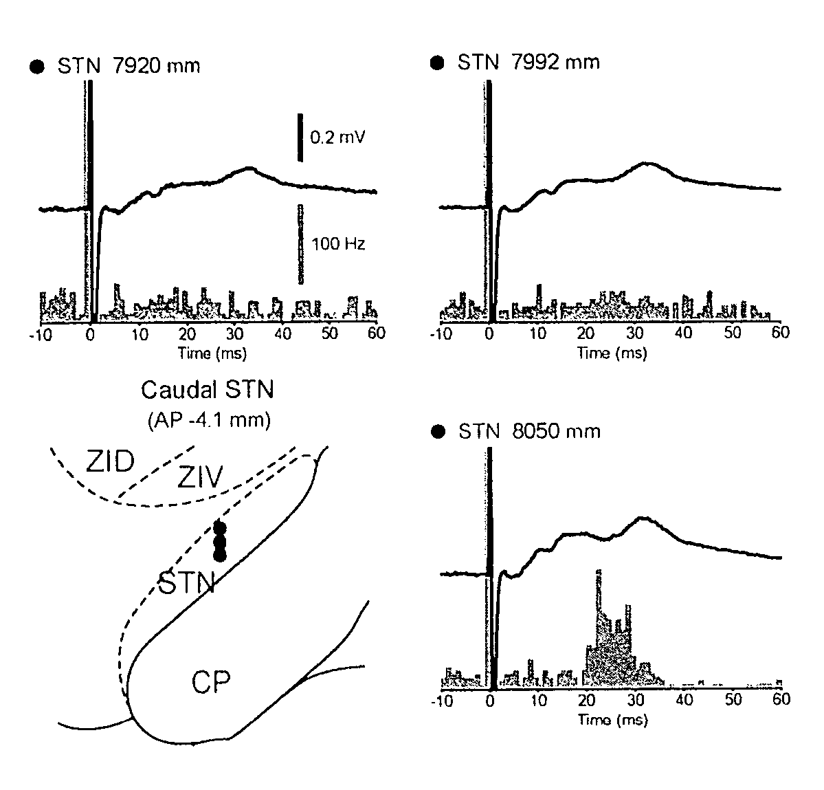
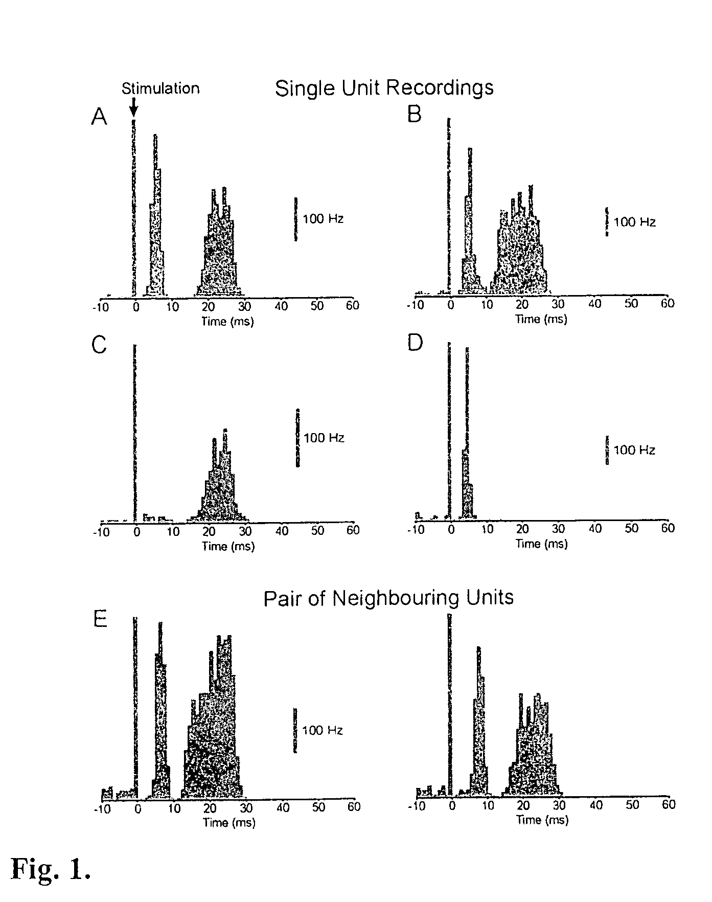
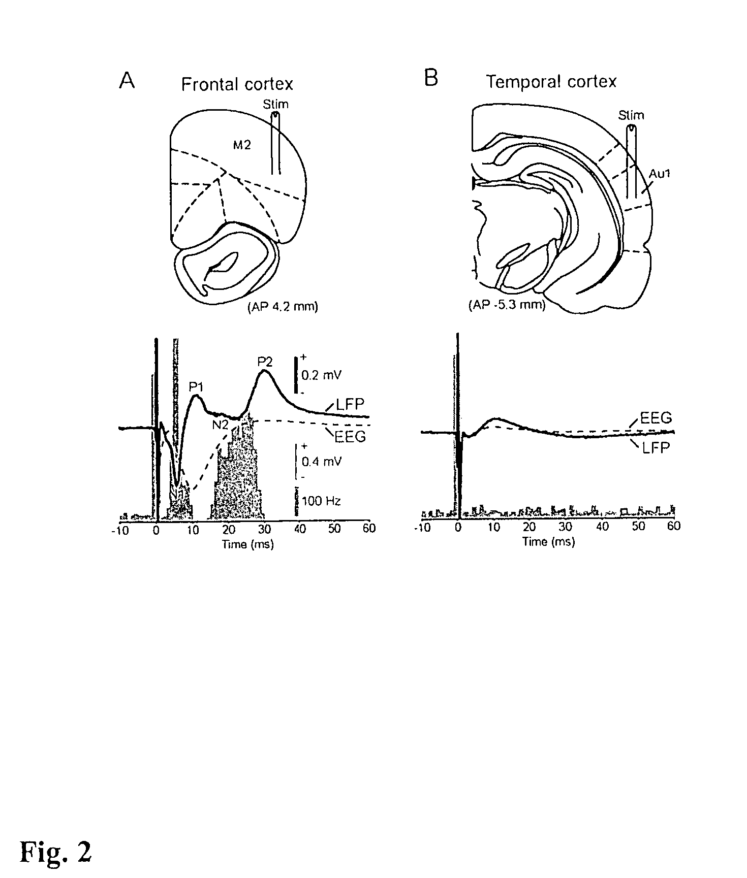
[0017]Synchronised activity is dependent on topography and the intensity of input. The stereotypical profile of the LFP demonstrates utility for locating the STN in clinical as well as non-clinical settings.
[0020]Taken together, the inventors have shown that stimulation of structures within the CNS itself, for example, the cerebral cortex, can generate specific FPs in the BG and that characteristic FPs evoked by CNS stimulation can be used to accurately identify these neural centres in a clinical setting, e.g. during the surgical implantation of DBS-type or electrocoagulation-type electrodes.
[0022]The use of evoked LFPs to accurately identify the location of neural centres of the CNS in a given patient provides for a more accurate placement of DBS or coagulation electrodes and thus, improved therapeutic potential of the DBS treatment by combating some of the major disadvantages associated with surgical intervention as a treatment for Parkinson's disease, dystonia and epilepsy. The methods provided by the inventors thus improve the available treatments for patients exhibiting PD, PD-like or epileptic symptoms, including tremor, or other motor dysfunctions.
[0024]Field potentials, such as LFPs, provide robust and representative electrophysiological data that can be easily and quickly acquired during or after electrode implantation. Furthermore, because the LFP can be recorded using the therapeutic electrode(s), the risk of neuron damage, and chances of failure of the operation and therapy are reduced.
[0025]The inventors have thus provided methods of location of selected CNS neural centres, methods of directing electrodes to, and electrode placement at, these centres leading to improved methods of treatment of patients in need of treatment by DBS or electrocoagulation.

Problems solved by technology

Whereas DBS techniques utilise electrical currents to stimulate the target neural centre, electrocoagulation techniques involve the supply of electrical currents to heat the neural centre, effectively burning out the neural centre and destroying its activity.
Whilst MRI and other imaging techniques can provide general information on the location of anatomical structures in a given individual, these techniques often cannot provide detailed information on the exact spatial location of specific neural centres in the BG and, the CNS in general.
High standards of technical equipment and practitioner expertise are required to perform these micro-recordings, both of which are not easily available.
Moreover, the use of fine micro-electrodes carries an increased risk of neuronal tissue damage by puncture of blood vessels and neurons during implantation of the micro-electrode.
Thus, the surgical implantation of the requisite electrodes for DBS treatment remains seriously disadvantaged by the difficulties associated with unequivocally identifying the STN itself (i.e. distinguishing the STN from surrounding structures) and, once identified, locating the (motor) area of STN that is most useful for subsequent electrical manipulation.
The complex interactions within cortical and basal ganglia circuits make the theoretical extrapolation of single neuron responses, as measured using micro-electrode techniques, to the population level a difficult task.
Accordingly a number of technical difficulties and problems exist in the unequivocal identification of a neural centre in the CNS.
In particular, the inaccuracies associated with current methods for identifying the position of neural centres in the BG, such as the STN, and GP provides a significant obstacle to the treatment of patients by electrode-based therapies, such as DBS and electrocoagulation.

Method used


Image

  • Methods of neural centre location and electrode placement in the central nervous system
  • Methods of neural centre location and electrode placement in the central nervous system
  • Methods of neural centre location and electrode placement in the central nervous system

Examples


Embodiment Construction

[0097]Specific details of the best mode contemplated by the inventors for carrying out the invention are set forth below, by way of example. It will be apparent to one skilled in the art that the present invention may be practiced without limitation to these specific details.

Materials and Methods

Electrophysiological Recordings and Labeling of Recording Sites

[0098]Experimental procedures were carried out on adult male Sprague-Dawley rats (Charles River, Margate, UK) and were conducted in accordance with the Animals (Scientific Procedures) Act, 1986 (UK) and the European Communities Council Directive (86 / 609 / EEC).

[0099]Electrophysiological recordings were made in 13 rats (230-350 g). Anaesthesia was induced with isoflurane (ISoflo™, Schering-Plough Ltd., Welwyn Garden City, UK) and maintained with urethane (1.3 gkg−1, i.p.; ethyl carbamate, Sigma, Poole, UK), and supplemental doses of ketamine (30 mgkg−1, i.p.; Ketaset™, Willows Francis, Crawley, UK) and xylazine (3 mgkg−1, i.p.; Romp...


PUM


Abstract

A method of locating the position of a selected neural centre in the central nervous system of an animal is disclosed. The method comprises the steps of (a) stimulating neurons at a first central nervous system position; (b) measuring the field potential evoked at a second central nervous system position; and (c) comparing the evoked field potential against a known evoked field potential from the neural centre.

Description

[0001]This application claims priority to U.S. Provisional Application 60 / 502,434 filed Sep. 12, 2003, the disclosure of which is incorporated herein by reference.FIELD OF THE INVENTION [0002]The present invention relates to methods of locating the position of a selected neural centre in the central nervous system, to methods of directing an electrode to, and placement at, these neural centres and to treatment of patients in need of treatment by electrical stimulation or electrocoagulation of these neural centres.BACKGROUND OF THE INVENTION [0003]The basal ganglia (BG) are a group of subcortical brain nuclei in the central nervous system (CNS) that are intimately involved in movement and cognition17, 27, 26. The cerebral cortex, the principal afferent of the BG, directly transfers information to the BG via projections to the neostriatum (NS) and subthalamic nucleus (STN). The STN is a small, deep-lying neural centre in the brain that is critical for movement and some cognitive proce...

Claims


Application Information

Patent Timeline
Patent Type & Authority Patents(United States)
IPC IPC(8): A61B5/05A61B18/18A61N1/00A61B5/04A61B18/14A61N1/36
CPCA61N1/3605A61B18/14A61N1/36067A61N1/36064A61N1/36082
Inventor MAGILL, PETER JAMESBOLAM, JOHN PAUL
Owner MEDICAL RESEARCH COUNCIL
Why Eureka
Try Eureka