Plasma lighting system having thin metallic film resonator

a technology of metallic film and plasma light, which is applied in the direction of energy-saving lighting, magnetic discharge control, sustainable buildings, etc., can solve the problems of high price, short life, and inefficient light emission, and achieve low energy transfer rate and high light emission efficiency.

Inactive Publication Date: 2009-09-01
LG ELECTRONICS INC
View PDF6 Cites 1 Cited by
  • Summary
  • Abstract
  • Description
  • Claims
  • Application Information

AI Technical Summary

Benefits of technology

[0010]Therefore, Therefore, an objective of the present invention is to provide an electrodeless sulfur lamp with a high efficiency of emitting light without using a short-lived magnetron which is low in energy transfer rate.

Problems solved by technology

The incandescent lamp is excellent in color rendition and small-sized, but inefficient in emitting light and short-lived.
The HID lamp is light-efficient and long-lived, but requires much time between switching off light and switching on light.
The PLS lamp is much long-lived and efficient in emitting light, compared to the others, but high-priced, and low in power consumption.
A problem with the conventional electrodeless sulfur lamp is that the life of magnetron is life-shorted, compared to the quartz bulb.
However, the design life of the magnetrons is currently only about 15,000 to 20,000 hours.
The development in the magnetron generating the micro-wave is relatively slow, which contributes to lowering an energy transfer rate.

Method used


Image

  • Plasma lighting system having thin metallic film resonator
  • Plasma lighting system having thin metallic film resonator
  • Plasma lighting system having thin metallic film resonator

Examples


second embodiment

[0031]the present invention is now described.

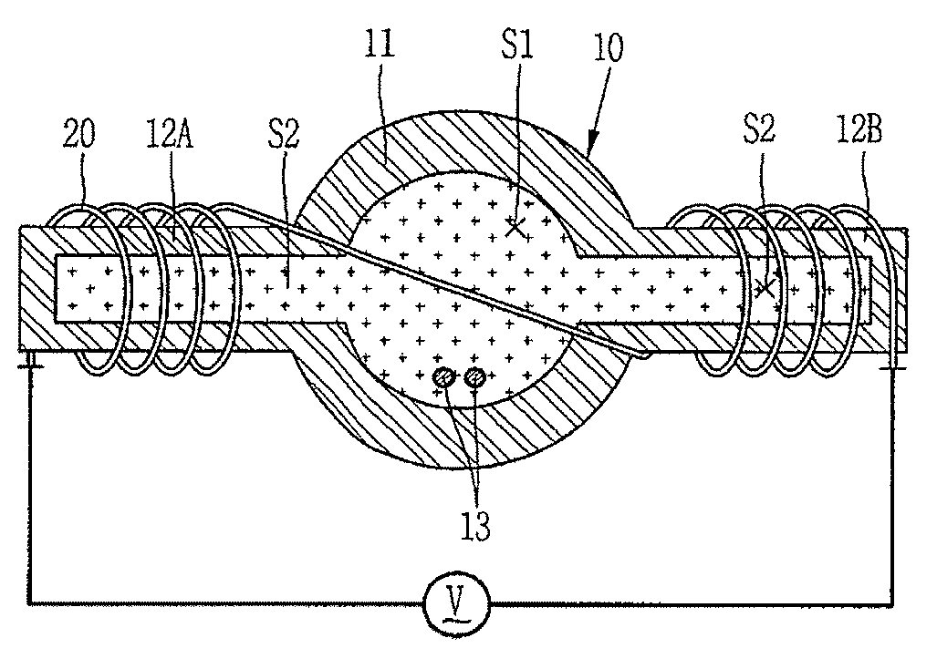
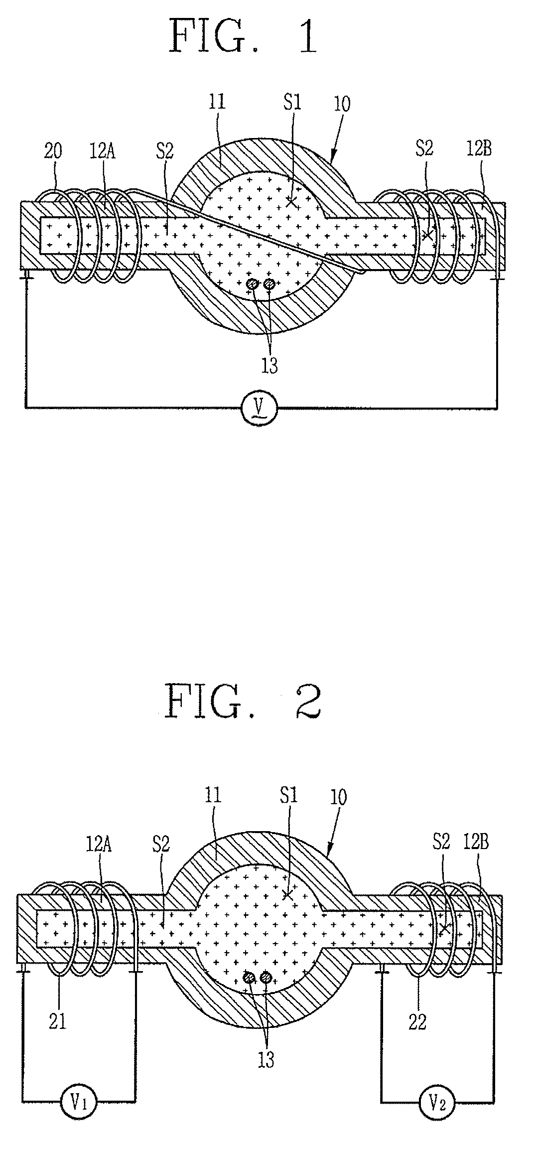
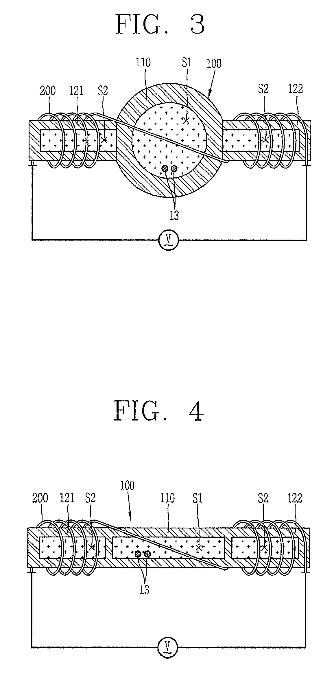
[0032]The transparent bulb 100 includes the main discharge sphere 110 and the subsidiary discharge rods 121 and 122 which are separately formed, as shown in FIGS. 3 and 4. The main discharge material, such as sulfur. Is contained in a space “S1” . The subsidiary electric discharge material, such as argon or neon, may be contained in the space “S1” , along with the main electric discharge material. The subsidiary electric discharge material only is contained in a space of the subsidiary electric discharge rods 121 and 122

first embodiment

[0033]As in the first embodiment, the coil may be wound around one subsidiary electric discharge rod 121 and then continuously around the other subsidiary electric discharge rod 122, with both ends of the coil connected to the power supply, or may be independently wound around each of the subsidiary electric discharge rods 121 and 122, with both ends of each connected to separate power supplies “V1” and “V2,” respectively.

[0034]In a case where the main electric discharge material is contained in the main electric discharge sphere 110 and the subsidiary electric discharge in the subsidiary electric discharge rods 121 and 122, load to the main electric discharge sphere 110 is reduced, thereby relatively strengthening combination of magnetic fields. This gives rise to the stable electric discharge.

[0035]The addition of the subsidiary electric discharge rods to the main electric discharge sphere and the winding of the coil around the subsidiary electric discharge rods enables the sulfur...


PUM


Abstract

Provided is an electrodeless sulfur lamp including a power supply supplying electrical power, a transparent bulb which has a space inside it, with sulfur being contained in the space, and a coil connected to the power supply, which is wound around an outside surface of the transparent bulb and which induces electric discharge by combining magnetic fields. The exclusion of the magnetron in the sulfur lamp increase a system efficacy and saves a cost for the magnetron. Also, it is possible to prevent the coil from blocking light emitted from the main electric discharge sphere 11, because the coil is not wound around the main electric discharge sphere.

Description

[0001]This application claims priority under 35 U.S.C. § 119 to Korean Patent Application No. 2005-0093592, filed in Korea on Oct. 5, 2005, the entirety of which is hereby incorporated by reference.BACKGROUND OF THE INVENTION[0002]1. Field of the Invention[0003]The present invention is related to an electrodeless sulfur lamp, and particularly to an electrodeless sulfur lamp, which do not use magnetron.[0004]2. Description of the Background Art[0005]There are various sources of lighting: an incandescent lamp using heat radiation, a fluorescent lamp of which an electric discharge tube uses a fluorescent material, a high intensity discharge (HID) lamp using electric discharge within a high-pressurized gas or steam, and a plasma lighting system (PLS) lamp using electrodeless discharge.[0006]The various lamps have their respective advantages and disadvantages. The incandescent lamp is excellent in color rendition and small-sized, but inefficient in emitting light and short-lived. A switc...

Claims


Application Information

Patent Timeline
Patent Type & Authority Patents(United States)
IPC IPC(8): H01J5/16
CPCH01J61/12H05B41/2806H01J65/048Y02B20/22Y02B20/00H01J61/16
Inventor PARK, BYEONG-JU
Owner LG ELECTRONICS INC
Why Eureka
Try Eureka