
Apparatus, system, and method for controlling speed of a cooling fan

a technology of fan speed and fan control, applied in the direction of motor/generator/converter stopper, dynamo-electric converter control, instruments, etc., can solve the problems of inability to adjust the speed of fixed-speed fans, often dissipating a lot of power and generating a lot of heat while in operation, and generating a lot of noise, etc., to achieve accurate adjustment of fan speed

Inactive Publication Date: 2009-09-01
INT BUSINESS MASCH CORP
View PDF5 Cites 58 Cited by
  • Summary
  • Abstract
  • Description
  • Claims
  • Application Information

AI Technical Summary

Problems solved by technology

Electronic equipment, such as computers, servers, data storage devices, video game consoles, etc., often dissipate a lot power and generate a lot of heat while in operation.
Fixed speed fans are sometimes used, however, fixed speed fans are not able to vary the speed of the fan and typically must be designed for worst-case operating conditions.
Fixed speed fans are inefficient and undesirable because they run at full capacity at all times. Consequently, fixed speed fans produce more audible noise and diminish fan operating life.
Multi-speed fans are a step in the right direction toward quieter, more efficient electronic devices, but ultimately may not offer as much efficiency or noise reduction as may be desired.
Fan control based on temperature alone, however, is not ideal because the fan speed control is reactive instead of proactive.
In addition, other components may also be heating up and the heating may not be linear with the component where temperature is sensed.

Method used


Image

  • Apparatus, system, and method for controlling speed of a cooling fan
  • Apparatus, system, and method for controlling speed of a cooling fan
  • Apparatus, system, and method for controlling speed of a cooling fan

Examples


Embodiment Construction

[0034]Many of the functional units described in this specification have been labeled as modules, in order to more particularly emphasize their implementation independence. For example, a module may be implemented as a hardware circuit comprising custom VLSI circuits or gate arrays, off-the-shelf semiconductors such as logic chips, transistors, or other discrete components. A module may also be implemented in programmable hardware devices such as field programmable gate arrays, programmable array logic, programmable logic devices or the like.

[0035]Modules may also be implemented in software for execution by various types of processors. An identified module of executable code may, for instance, comprise one or more physical or logical blocks of computer instructions which may, for instance, be organized as an object, procedure, or function. Nevertheless, the executables of an identified module need not be physically located together, but may comprise disparate instructions stored in d...


PUM


Abstract

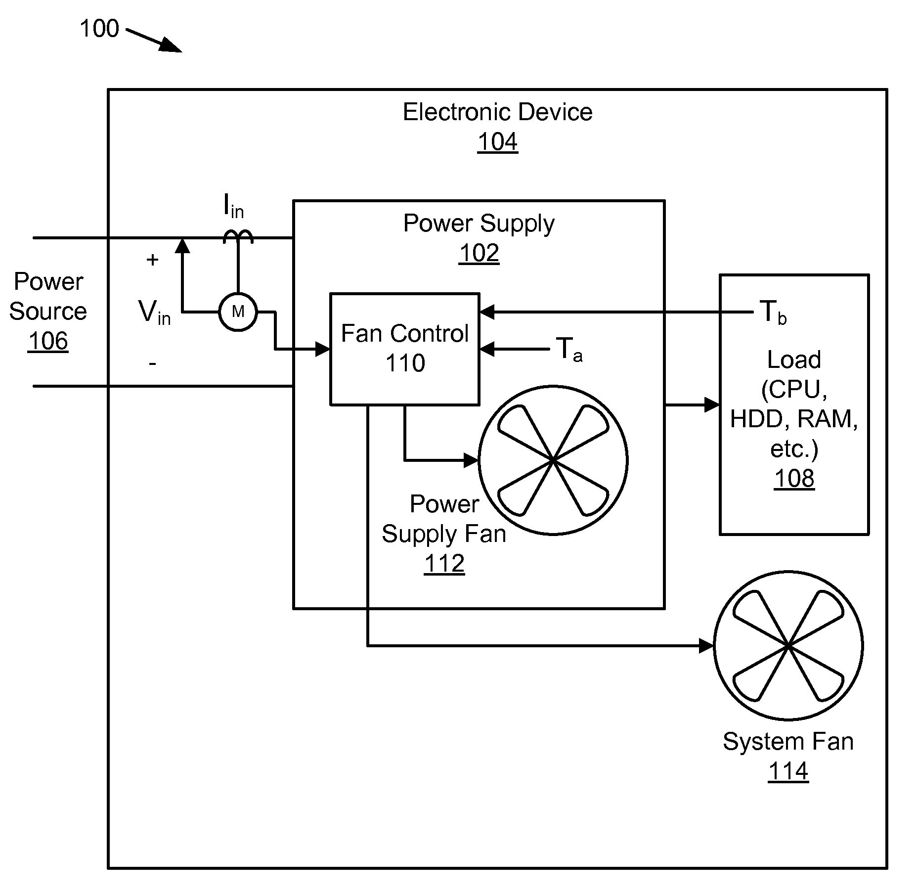
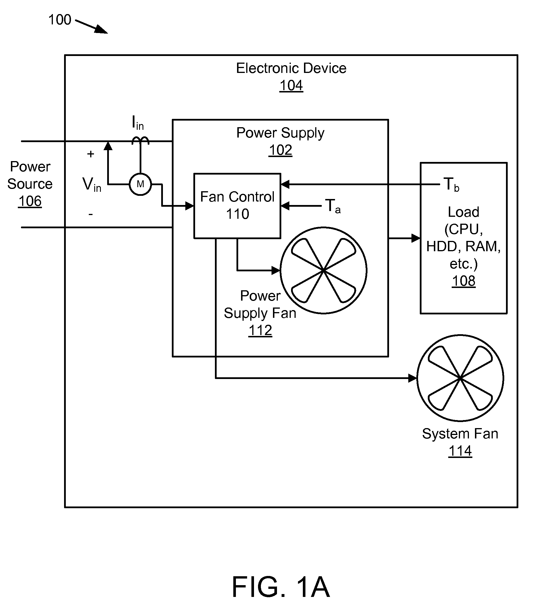
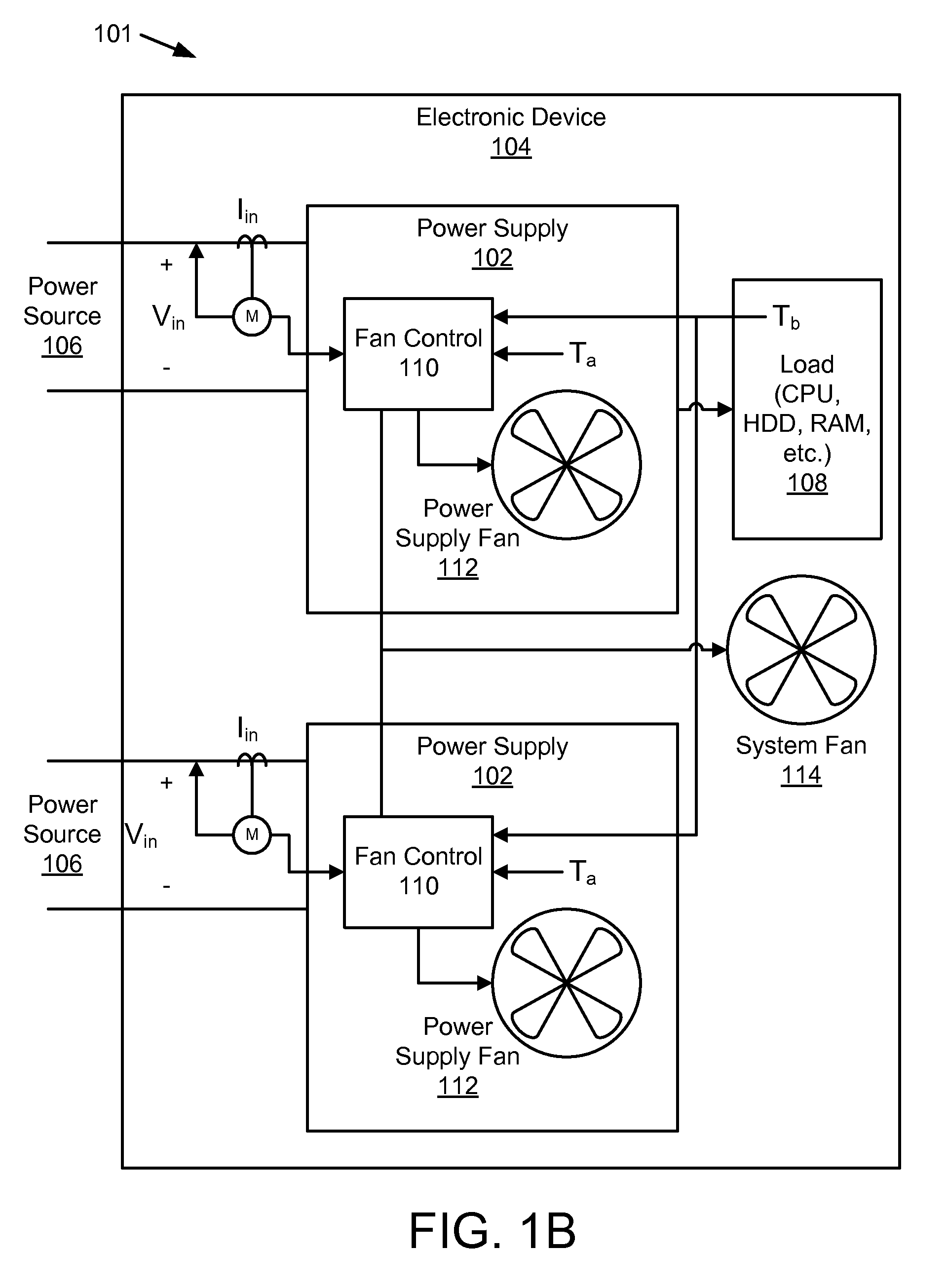
An apparatus, system, and method are disclosed for controlling fan speed. A power sensing module senses input voltage and current of a power supply. The power supply includes one or more stages and regulates at least one output bus. A power calculation module calculates input power from the input voltage and the input current. A temperature sensing module senses an ambient temperature and / or a temperature at a component cooled by a fan. A fan speed calculation module calculates a fan speed signal for the fan. The fan speed signal is a function of the input power calculated by the power calculation module and the sensed temperature sensed by the temperature sensing module for at least a portion of a fan speed range. A fan speed transmission module transmits the fan speed signal to the fan and adjusts a fan speed based on the fan speed signal.

Description

BACKGROUND OF THE INVENTION[0001]1. Field of the Invention[0002]This invention relates to fan control and more particularly relates to cooling fan control using input power and temperature.[0003]2. Description of the Related Art[0004]Electronic equipment, such as computers, servers, data storage devices, video game consoles, etc., often dissipate a lot power and generate a lot of heat while in operation. Often cooling fans are required to ensure normal equipment operation and to meet reliability goals. Fixed speed fans are sometimes used, however, fixed speed fans are not able to vary the speed of the fan and typically must be designed for worst-case operating conditions. Fixed speed fans are inefficient and undesirable because they run at full capacity at all times. Consequently, fixed speed fans produce more audible noise and diminish fan operating life.[0005]Variable speed fans are commonly used in electronic devices and are capable of varying the speed of the fan. Some variable ...

Claims


Application Information

Patent Timeline
Patent Type & Authority Patents(United States)
IPC IPC(8): G05D23/275
CPCG05D23/1917G05D23/1934G06F1/206H05K7/20209Y02D10/00F04D27/004F05D2270/303F05D2270/335Y02B30/70
Inventor CHUNG, CHU TEDISHMAN, C. CHARLESLIN, JEN-CHINGLINDFORS, EINO A.
Owner INT BUSINESS MASCH CORP
Learn More