Distributed communication equipment architectures and techniques

a technology of communication equipment and distribution network, applied in the field of communication, can solve the problems of reducing the service quality of communication, reducing the service life of communication equipment, and avoiding the distribution of substantial functionality, so as to achieve cost-effective and scalable, expand the access network, and reduce the cost of communication equipmen

Active Publication Date: 2009-09-01
RPX CORP
View PDF19 Cites 0 Cited by
  • Summary
  • Abstract
  • Description
  • Claims
  • Application Information

AI Technical Summary

Benefits of technology

[0009]Some embodiments of the invention address the problem of delivering DSL services to a large number of subscribers in a cost effective and scalable manner. A scalable, distributed access node system architecture is provided, and may include one or more host systems connected to respective groups of satellite expansion shelf systems and / or sealed expansion modules (SEMs), which have DSL interfaces to connect to subscriber Customer Premises Equipment (CPE). In one embodiment, the physical layout of the expansion shelf system is identical to that of the host system, so that it can easily be converted to another host system, to satisfy network expansion requirements for instance. This can be an important advantage, for example, to service providers needing an easy and cost effective migration plan for expanding their access networks as their subscriber base grows.
[0010]Other embodiments of the invention provide flexibility in the provisioning of communication links of a distributed access node system to be either network links or access links. This flexibility allows network coverage to be expanded in accordance with subscriber demand, which can be particularly important for enhanced DSL services such as so-called “Triple Play” services of Internet, video, and voice, for instance. Both dedicated and configurable interfaces, illustratively Gigabit Ethernet (Gig-E) interfaces, are provided at a host system of the distributed access node system. Configurable interfaces may be useful, for example, to reduce the number of dedicated physical connectors such as Small Form-factor Pluggable (SFP) ports on an electronic circuit card faceplate at the host system, thereby providing cost and space savings.

Problems solved by technology

In some types of communication system such as systems for providing Digital Subscriber Line (DSL) services, communication service quality degrades as distance from access communication equipment increases.
However, this approach tends to be cost prohibitive in terms of both initial equipment costs and continuing management and maintenance costs.
According to these solutions, substantial functionality is duplicated instead of being distributed.
This increases the cost of an overall system.
However, this solution requires not only typical CO equipment, but also repeater equipment, at an overall increase in cost.

Method used


Image

  • Distributed communication equipment architectures and techniques
  • Distributed communication equipment architectures and techniques
  • Distributed communication equipment architectures and techniques

Examples


Embodiment Construction

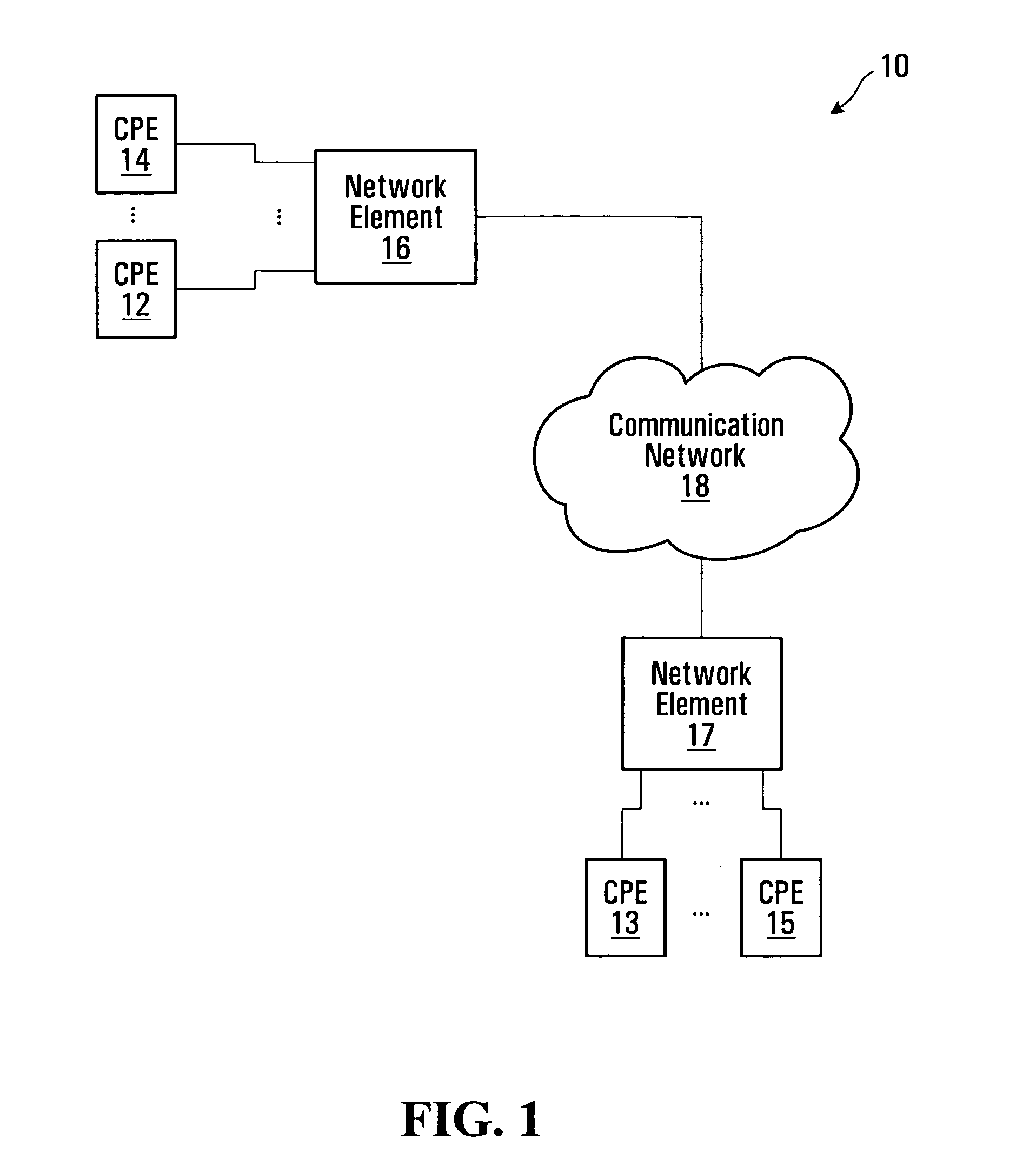
[0041]FIG. 1 is a block diagram of a communication system 10, in which embodiments of the invention may be implemented. The communication system 10 includes multiple CPE installations 12 / 14, 13 / 15, network elements 16, 17, and a communication network 18. Although only four CPEs 12 / 14, 13 / 15 and two network elements 16, 17 have been shown in FIG. 1 to avoid congestion, many more CPEs and network elements may be connected to the communication network 18. It should therefore be appreciated that the system of FIG. 1, as well as the contents of the other drawings, are intended solely for illustrative purposes, and that the present invention is in no way limited to the particular example embodiments explicitly shown in the drawings and described herein.

[0042]The CPEs 12 / 14, 13 / 15 represent communication equipment, illustratively end user communication devices, configured to receive and / or transmit communication signals. Although shown as being directly connected to the network elements 16...


PUM


Abstract

Distributed communication equipment architectures and techniques are disclosed. A host system includes an expansion unit through which control information and communication traffic may be exchanged with an expansion system. The expansion system is thereby controllable by a controller at the host system, significantly simplifying the design and reducing the cost of the expansion system. The expansion unit for a host system may also provide one or more configurable communication link interfaces. Each configurable interface may be independently configured as a network-side interface for connection to upstream communication equipment or as an access-side expansion interface for connection to an expansion system, allowing provisioning of network and access interfaces at the host system as needed.

Description

CROSS-REFERENCE TO RELATED APPLICATION[0001]This application is related to the commonly assigned and co-pending U.S. patent application Ser. No. 11 / 264,451, entitled “REMOTE CONTROL AND CONTROL REDUNDANCY FOR DISTRIBUTED COMMUNICATION EQUIPMENT”, filed of even date herewith, the entire contents of which are incorporated herein by reference.FIELD OF THE INVENTION[0002]This invention relates generally to communications and, in particular, to distributed communication equipment architectures and related techniques.BACKGROUND[0003]In some types of communication system such as systems for providing Digital Subscriber Line (DSL) services, communication service quality degrades as distance from access communication equipment increases. One possible approach to alleviate this type of problem is to deploy access equipment closer to customers. However, this approach tends to be cost prohibitive in terms of both initial equipment costs and continuing management and maintenance costs.[0004]Dist...

Claims


Application Information

Patent Timeline
Patent Type & Authority Patents(United States)
IPC IPC(8): H04L12/28G06F15/16H04L12/56
CPCH04Q11/04H04Q2213/13003H04Q2213/1301H04Q2213/13039H04Q2213/13092H04Q2213/13191H04Q2213/13106H04Q2213/13109H04Q2213/13166H04Q2213/13178H04Q2213/13094
Inventor ABOUKARR, BAKRIAYDIN, ARKINCONDIE, MARY ANNSULLIVAN, WILFREDTOMILSON, ANDREW GORDONLANDRY, GUYPAUWELS, BART JOSEPH GERARDPEETERS, RONNY JOZEF LEONHOOGHE, KOEN
Owner RPX CORP
Why Eureka
Try Eureka