Joint member for wiper blade and wiper blade

a technology of wiper blade and joint member, which is applied in the field of joint member, can solve the problems of harmful vibration between the wiper arm b and the wiper blade main body, and achieve the effect of easy and firmly joining the wiper arm and low cos

Inactive Publication Date: 2009-09-15
DENSO WIPER SYST INC
View PDF24 Cites 11 Cited by
  • Summary
  • Abstract
  • Description
  • Claims
  • Application Information

AI Technical Summary

Benefits of technology

[0014]It is therefore an object of the present invention to provide a joining member capable of easily and firmly joining a wiper arm with U-hook portions of various types to a wiper blade main-body at low cost.
[0028]Because the joint member of the present invention comprises a fitting member (for example, fitting members 21, 51) which is mounted on a wiper blade main-body (for example, a wiper blade main-body 1) and fits against a wiper arm (a wiper arm 10), a fixing member (for example, fixing members 22, 52) which holds and fixes the wiper arm between the fixing member and the fitting member, and a flexible connecting portion (for example, connecting portions 23, 53) which connects the fitting member and the fixing member together, and because, for example, the fitting member fits into an inner side of a hook portion (for example, a U-hook portion 11) provided in the wiper arm and the fixing member supports the hook portion by sandwiching the hook portion between the fixing member itself and the fitting member, the fixing member can relatively freely moving with respect to the fitting member in a range in which the connecting portion is deformed. Therefore, the wiper arm is easily joined to the joint member. Also, because the joining work can be performed by mounting the fixing member on the fitting member and the hook portion, the work can be performed on the upper side of the wiper blade main-body and the worker can perform the joining work easily while visually checking work positions. Also, because the flexible connecting portion holds the hook portion between the fitting member and the fixing member by warping, a simple structure can be obtained in comparison with a case where a complex connecting mechanism is adopted and it is possible to reduce cost. Also, the adaptable shape of the hook portion will not be limited by the connecting structure of the fitting member and the fixing member. Further, because the fitting member and the fixing member can be designed as separate members and the configurations of the fitting member and fixing member will not be limited by the manner of their mutual connection (connecting structure), it is possible to appropriately select the sizes and shapes of the fitting member and fixing member so that a strong holding force is ensured. As a result, it is possible to effectively suppress a vibration between the wiper arm and the wiper blade. It is also possible to appropriately set the rotational resistance of the wiper arm and wiper blade.
[0029]By using a plate-like member as the connecting portion, it is ensured that the connecting portion has high durability which hardly causes fracture while providing appropriate flexibility (the property of being easily bent).
[0031]When the hook portion is supported by being sandwiched between a front portion (for example, a front transverse plate 41, a front portion 52B) and the fitting member, it is possible to positively fix the hook portion.
[0032]When the fixing member supports the hook potion by sandwiching the hook portion in such a manner that the side portion of the fixing member (for example, side plates 42, 43, a side portion 52C) abuts against part of the wiper blade main-body (for example, side portions 2B, 2C), a vibration between the wiper blade and the wiper arm can be effectively suppressed. Further, the wear of the connecting member can also be reduced.

Problems solved by technology

However, these conventional joint members have drawbacks as follows.
However, some vehicles have a construction that the wiper arm 10 cannot to rotate with respect to the wiper blade main-body 1 at such a large angle so that the joint member 100 cannot be applied to such vehicles.
As a result, during the operation of the wiper system, harmful vibrations occur between the wiper arm 10 and the wiper blade main-body 1.

Method used


Image

  • Joint member for wiper blade and wiper blade
  • Joint member for wiper blade and wiper blade
  • Joint member for wiper blade and wiper blade

Examples


Embodiment Construction

[0055]The embodiments of the present invention will be described below by referring to the accompanying drawings.

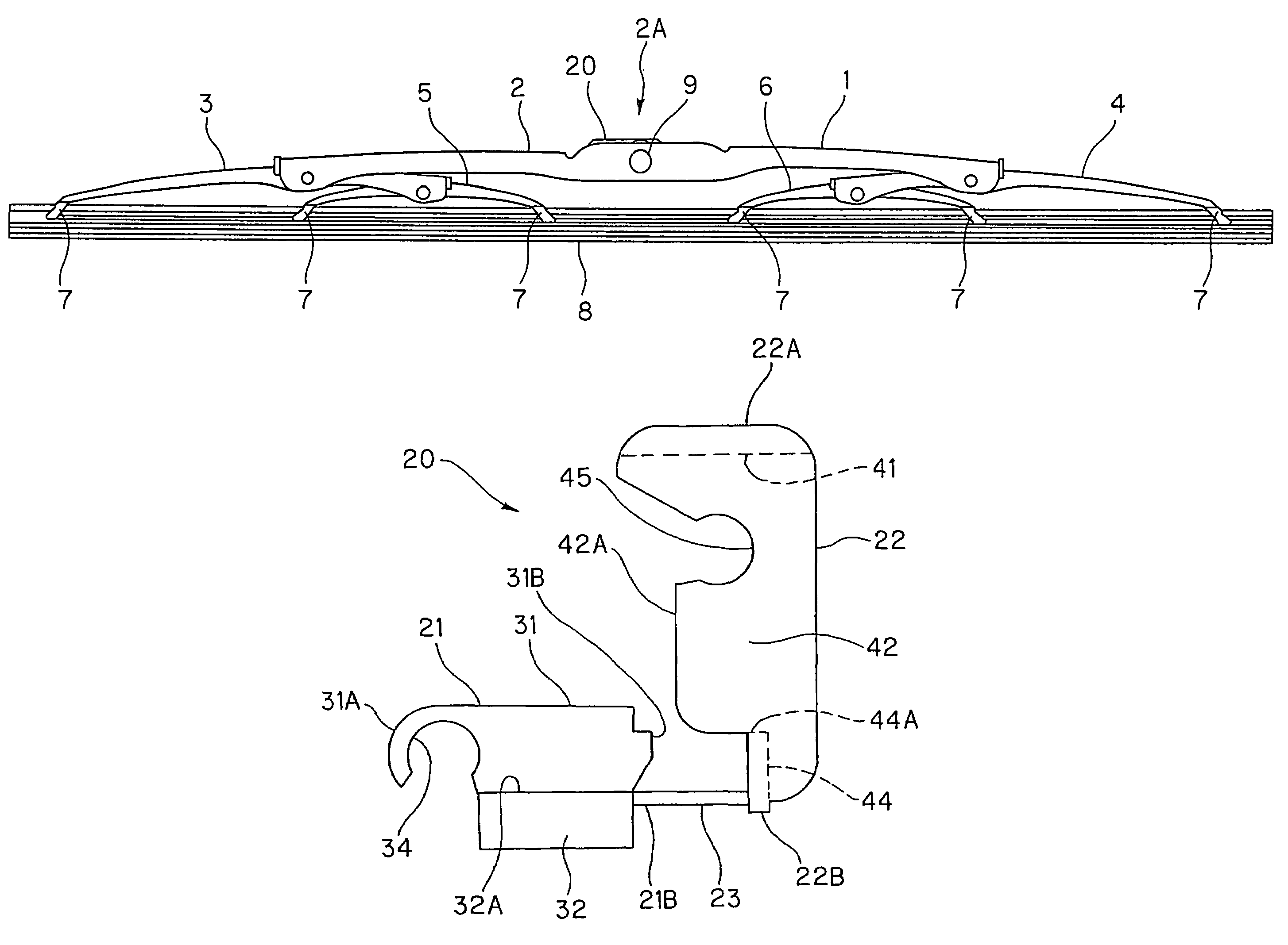
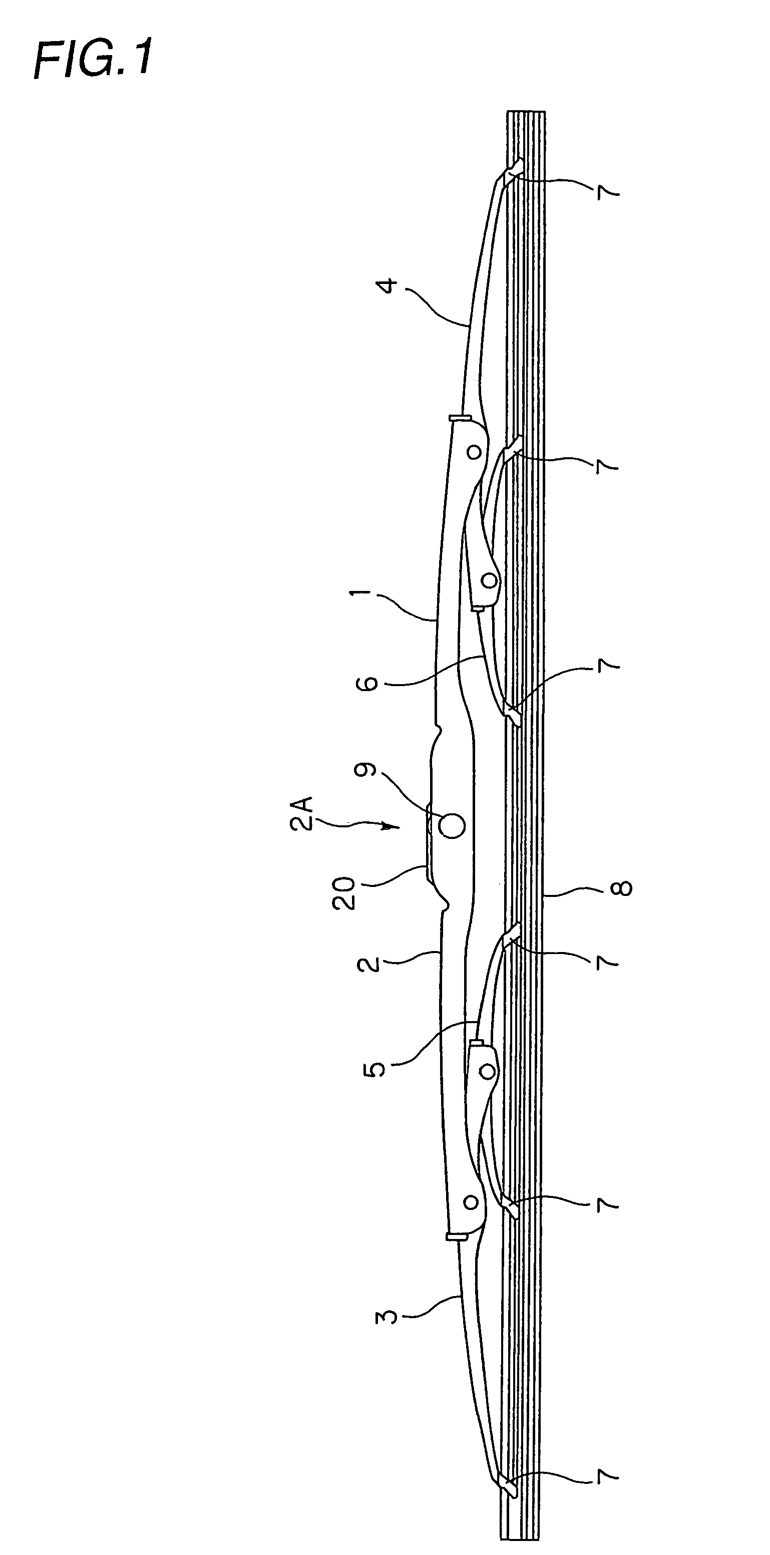
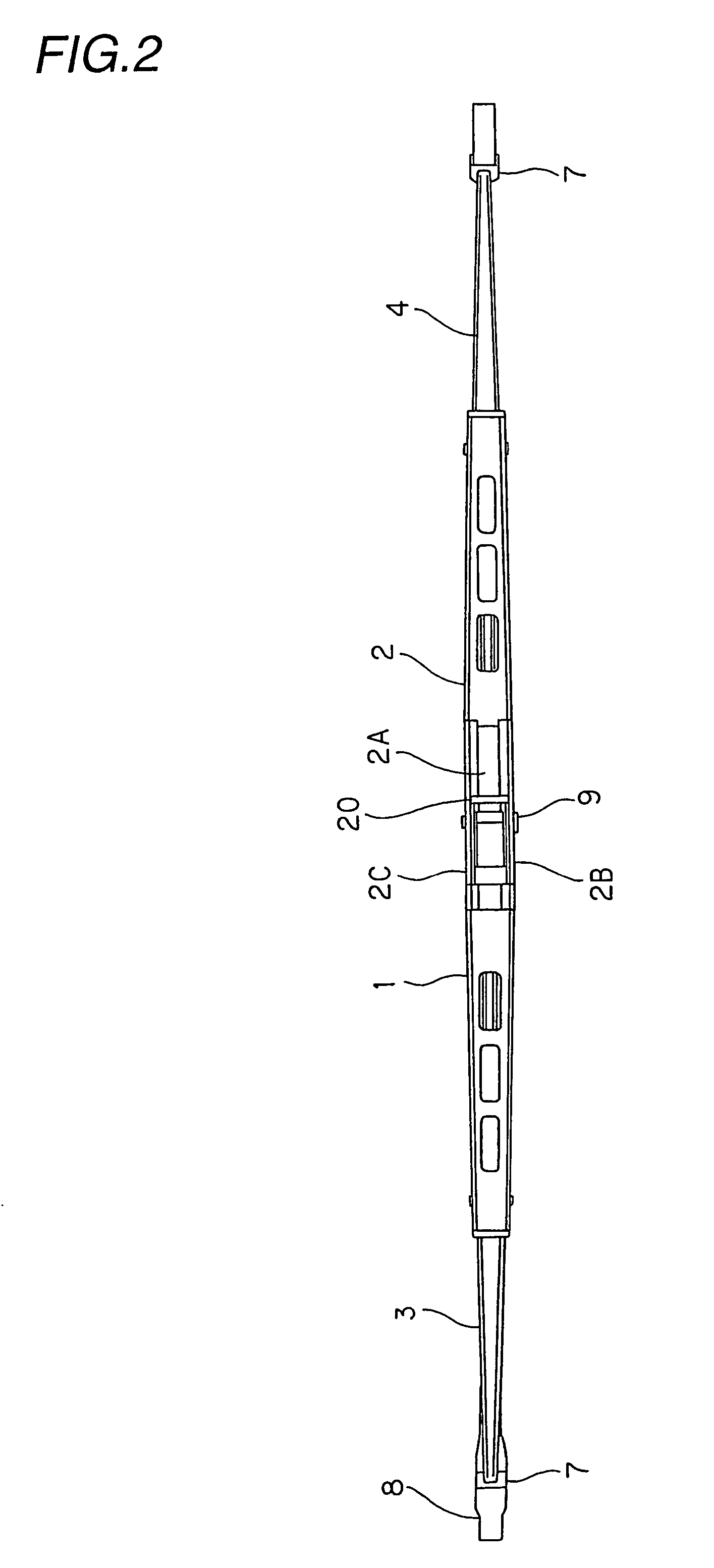
[0056]The general construction of a wiper blade is shown in FIGS. 1 and 2. As shown in the drawings, the wiper blade includes a wiper blade main-body 1 and a joint member 20 to connect this wiper blade main-body 1 and a wiper arm 10 (refer to FIGS. 6(A) to 6(E) etc.) together.

[0057]The wiper blade main-body 1 includes a primary lever 2, secondary levers 3, 4 which are rotatably supported on both ends of this primary lever 2, and yoke levers 5, 6 which are rotatably supported on inner side ends of a corresponding secondary levers 3, 4. Supporting claws 7 are formed on the outer side ends of the secondary levers 3, 4 and on both ends of the yoke levers 5, 6, and a wiper rubber 8 is attached to these supporting claws 7.

[0058]An opening 2A is formed substantially in the middle portion of the primary lever 2, and a mounting pin 9 spans across side portions 2B, 2C on both sides...


PUM


Abstract

A joint member capable of easily and firmly joining a wiper arm of various types (mainly the U-hook type) to a wiper blade main-body at low cost. The joint member 20 includes a fitting member 21 which a U-hook portion 11 of a wiper arm 10 fits to, a fixing member 22 which holds the hook portion 11 between the fixing member and the fitting member 21, and a flexible connecting portion 23 which connects a rear end 21B of the fitting member 21 and a rear end 22B of the fixing member 22 together. The fitting member 21 is rotatably mounted on a mounting pin 9 of a wiper blade main-body 1 and the angles of the wiper arm 10 and the wiper blade can be changed appropriately during mounting work. The U-hook portion 11 is held between a front transverse plate 41 of the fixing member 21 and a front end 21A of the fitting member 21. Both side plates 42 and 43 of the fixing member 21 abut against side portions 2B and 2C of the wiper blade main-body 1 so that a vibration between the wiper arm 10 and the wiper blade is prevented.

Description

FIELD OF THE INVENTION[0001]The present invention relates to a joint member to join a wiper blade to a wiper arm in a wiper system.DESCRIPTION OF THE RELATED ART[0002]A wiper system which is provided with a wiper blade, a wiper arm and a driving motor is well known in the art. The wiper blade includes a wiper rubber for wiping a surface of an object such as a windshield of a vehicle. The wiper blade is connected to the wiper arm which is linked to a driving motor through a link member. Thus, the driving motor drives the wiper blade through the wiper arm so that the wiper rubber wipes the object.[0003]In such a wiper system, the wiper arm may be connected to the wiper blade through a joint member which is connected to a curved portion (U-hook portion) of the wiper arm. FIGS. 17 to 19 show such joint members of prior art.[0004]As shown in FIGS. 17(A) to 17(D), a joint member 100 includes a fitting portion 101 which fits into a U-hook portion 11 of a wiper arm 10 and a pair of side pla...

Claims


Application Information

Patent Timeline
Patent Type & Authority Patents(United States)
IPC IPC(8): B60S1/40
CPCB60S1/4003B60S1/4016Y10T403/606B60S2001/4022B60S1/40
Inventor INOUE, YUUSUKE
Owner DENSO WIPER SYST INC
Why Eureka
Try Eureka