Leveling and aligning device

a leveling and aligning device technology, applied in the direction of threaded fasteners, couplings, rod connections, etc., can solve the problems of device not being used at all, difficult to adjust, and cannot be hidden in the body of the member, so as to achieve the effect of easy adjustmen

Active Publication Date: 2009-09-15
SILICON VALLEY AUTOMATION
View PDF30 Cites 33 Cited by
  • Summary
  • Abstract
  • Description
  • Claims
  • Application Information

AI Technical Summary

Benefits of technology

[0007]It is the principal object of the present invention to provide adjustable support of a member with respect to a base. The adjustable support can be easily adjusted, yet can be firmly locked in a given adjustment without stressing the material of either the base and the supported member or the adjustable support itself.
[0008]To achieve this object, the invention employs a threaded jacking sleeve, which can be threaded in and out of the body of the member. The bottom end of the jacking sleeve has a convex, spherical shape and mates with a concave, cone-shaped nest of a self-adjusting insert freely resting in a counterbore into the base surface. The insert further has a through hole in the center of the insert. Such solution gives so-called “line contact” distributing forces equally over a circle marked by the contact line between the ball and the cone. As the jacking sleeve is screwed in an out, the member rides down or up, resulting in precise setting of the required distance between the member and the base. The threaded jacking sleeve is turned by a driving washer with two protruding prongs on bottom. The driving washer has a through hole to accommodate a locking screw, and a coaxial counterbore to accommodate the head of the locking screw. The prongs engage a corresponding slot in the top of the jacking sleeve. When the jacking sleeve has been turned to achieve the desired distance between the member and the base, the adjustment can be securely locked in place by tightening a socket-head locking screw that is installed through the hole of the driving washer, the threaded jacking sleeve, the hole in the insert, and an opening in the base. The socket-head locking screw is threaded into a captive nut located in an oval groove in the base. The groove allows the captive nut to perform small x-y movements, but not to rotate. This solution effectively reduces stresses in the body of the member and in the adjustment device itself.
[0010]Another object of the present invention is to provide a solution for the problem described in the Background of the Invendon, and allow to continue the adjustment process, even if the assembler over rotates the jacking sleeve to the extent that the connection between the driving washer and the threaded jacking sleeve is lost.
[0011]To achieve this object, the ends of the prongs on the driving washer are slanted in such a way that during clockwise rotation, the prongs easily disengage from the threaded jacking sleeve's slot a fraction of a rotation earlier than they would if both sides of the prongs were of equal length and the prongs had flat ends. When the driving washer is turned counterclockwise, the prongs engage with the threaded jacking sleeve's slot wall, allowing the threaded jacking sleeve to be turned into the body of the member. To enhance effectiveness of this feature another pair of slants could be cut on corresponding edges of the threaded jacking sleeve's slot.

Problems solved by technology

The device provides reliable results, but is bulky, cannot be hidden in the body of the member, and is difficult to adjust.
In many applications, the device cannot be used at all due to limited accessibility.
There is a significant drawback to this solution, however.
If, during the adjustment process, a driving washer and an adjustment nipple lose connection, an assembler may be forced to perform a cumbersome recovery procedure.
Another drawback of this solution is existence of strong stresses in the bodies of the leveling devices.
Additionally, none of these solutions provides a means for locking the member in the given adjustment in relationship to the base, relying exclusively on gravity.

Method used


Image

  • Leveling and aligning device
  • Leveling and aligning device
  • Leveling and aligning device

Examples


Embodiment Construction

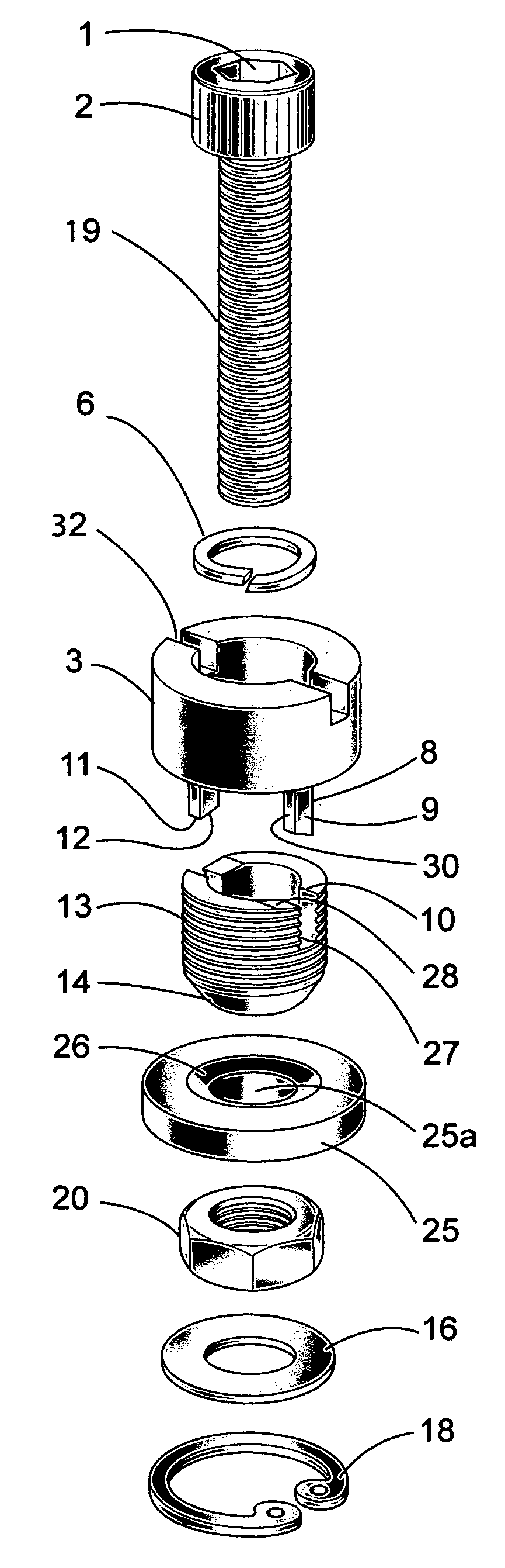
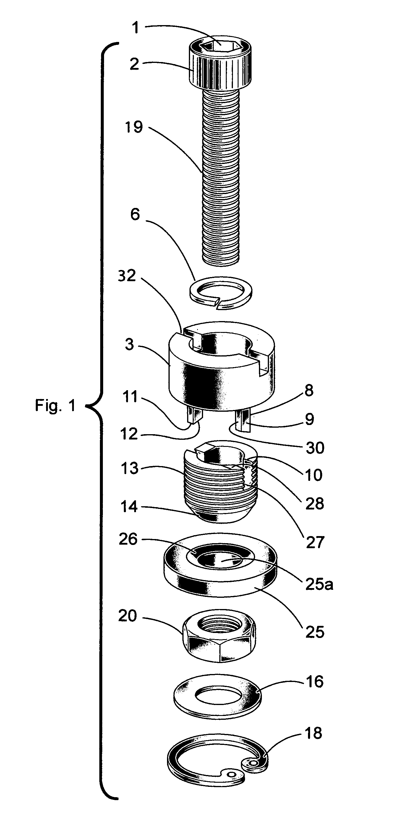
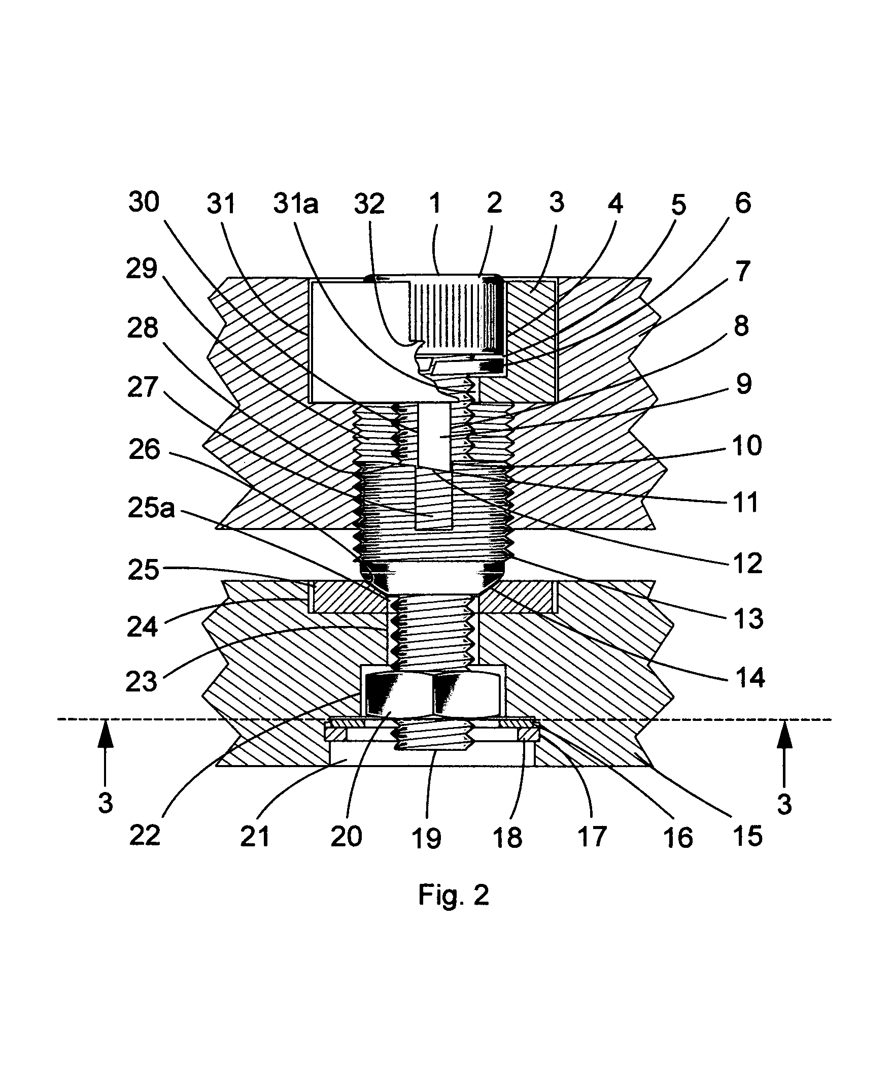
[0017]As shown in the accompanying drawings FIG. 1, FIG. 2, and FIG. 3 the preferred embodiment of the present invention that we will refer to as “Leveling and Aligning Device” comprises base 15 having round opening 23, and a shallow counterbore 24 for reception of insert 25 on the top. The bottom of base 15 also has an oval groove 22 for reception of captive nut 20 and grooved counterbore 21 for reception of washer 16 and internal retaining ring 18. FIG. 3 is a cross sectional view taken along line 3-3 in FIG. 2 and shows how the oval groove 22 prevents captive nut 20 from rotation. Grooved counterbore 21, washer 16 and internal retaining ring 18 are an example of providing a means for loosely securing captive nut 20 in oval groove 22, and can be replaced with any means providing the same function.

[0018]Means are provided for supported member 7 to be variably positioned with respect to base 15. Member 7 is adjusted with threaded jacking sleeve 13, which has slot 27 that engages wit...


PUM


Abstract

Leveling and aligning device by which the distance at which a member is supported with respect to a base may be altered and firmly locked in the given adjustment without creating stresses in either the body of the member and the base or the device by itself. The leveling and aligning device allows continuation of the adjustment process even in case of inadvertent disengagement of components of the device.

Description

TECHNICAL FIELD OF INVENTION[0001]Generally, the invention relates to devices, which adjustably support a member with respect to a base anchored to the ground, or standing on the floor, a machine or another device. This type of adjustable support is used in situations requiring precise leveling or alignment of a supported member. Typical applications would include leveling and controlling the height of tables, machines and instruments, or adjusting the vertical alignment of objects like lampposts, masts, and vertical rods. Other typical applications include alignment of assemblies such as lasers, robotic systems, and winding and reeling assemblies for films and tapes. Typically, these devices feature easy accessibility for readjustment and semi-permanent, firm locking of the member in the given adjustment.[0002]There are many ways of creating adjustable support of a member with respect to a base, patented or not. It is common knowledge that the member should be supported at three po...

Claims


Application Information

Patent Timeline
Patent Type & Authority Patents(United States)
IPC IPC(8): F16B5/02F16M7/00
CPCF16B5/0233F16M7/00F16B37/044Y10T403/75Y10T403/32598Y10T403/1624Y10T403/76
Inventor KIELCZEWSKI, GRZEGORZGERSHENZON, ELIKBERLINSKI, BOGDAN
Owner SILICON VALLEY AUTOMATION
Why Eureka
Try Eureka