Imaging Lens

a technology of imaging lens and lens barrel, applied in the field of imaging lens, can solve the problems of complex construction of lens barrel and enlarged lens system, and achieve the effect of avoiding aberration

Active Publication Date: 2009-09-15
TIANJIN OFILM OPTO ELECTRONICS CO LTD
View PDF10 Cites 8 Cited by
  • Summary
  • Abstract
  • Description
  • Claims
  • Application Information

AI Technical Summary

Benefits of technology

[0006]The invention has been made in view of the problem, and an object thereof is to provide a small, high-performance imaging lens which can implement a good focus adjustment without changing the overall length even though the imaging lens is a single focus lens made up of a relatively small number of lenses.
[0011]In the event that the imaging lens is configured as has been described above, the configuration and refractive power of each of the lenses are made appropriate by the lens configuration which is made up of a relatively small number of lenses such as four lenses in total, thereby making it possible to realize miniaturization and high performance. In addition, the second lens, which functions as the focusing lens, is disposed between the first lens and the third lens, and by shifting the second lens, the internal focusing type focus adjustment is implemented. In this case, since the focal length of the second lens is set properly in such a manner as to satisfy the conditional expression (X), the sensitivity of the second lens (a sensitivity to a change in the position of image plane associated with a shift of the focusing lens) and the lens shift amount at the time of adjusting focus are suppressed to appropriate values, whereby a good focus adjustment is implemented without changing the overall length of the lens.
[0014]By adopting this configuration, the configuration of each lens is optimized, which is advantageous in correcting aberrations. In addition, it becomes easy to secure a back focus which is necessary to dispose a cover glass or the like.0.15<R4A / f<0.35  (5),where, f denotes a focal length of the single focus imaging lens, and R4A a paraxial radius of curvature of the object side surface of the fourth lens.

Problems solved by technology

With focusing by moving the whole lens system, however, since the overall length is changed by focusing, there is caused a drawback that the construction of a lens barrel becomes complex and the lens system is enlarged.

Method used


Image

  • Imaging Lens
  • Imaging Lens
  • Imaging Lens

Examples


examples

[0079]Next, specific numeric examples of the imaging lens according to the embodiment will be described. Hereinafter, first to fifth numeric examples will be described altogether.

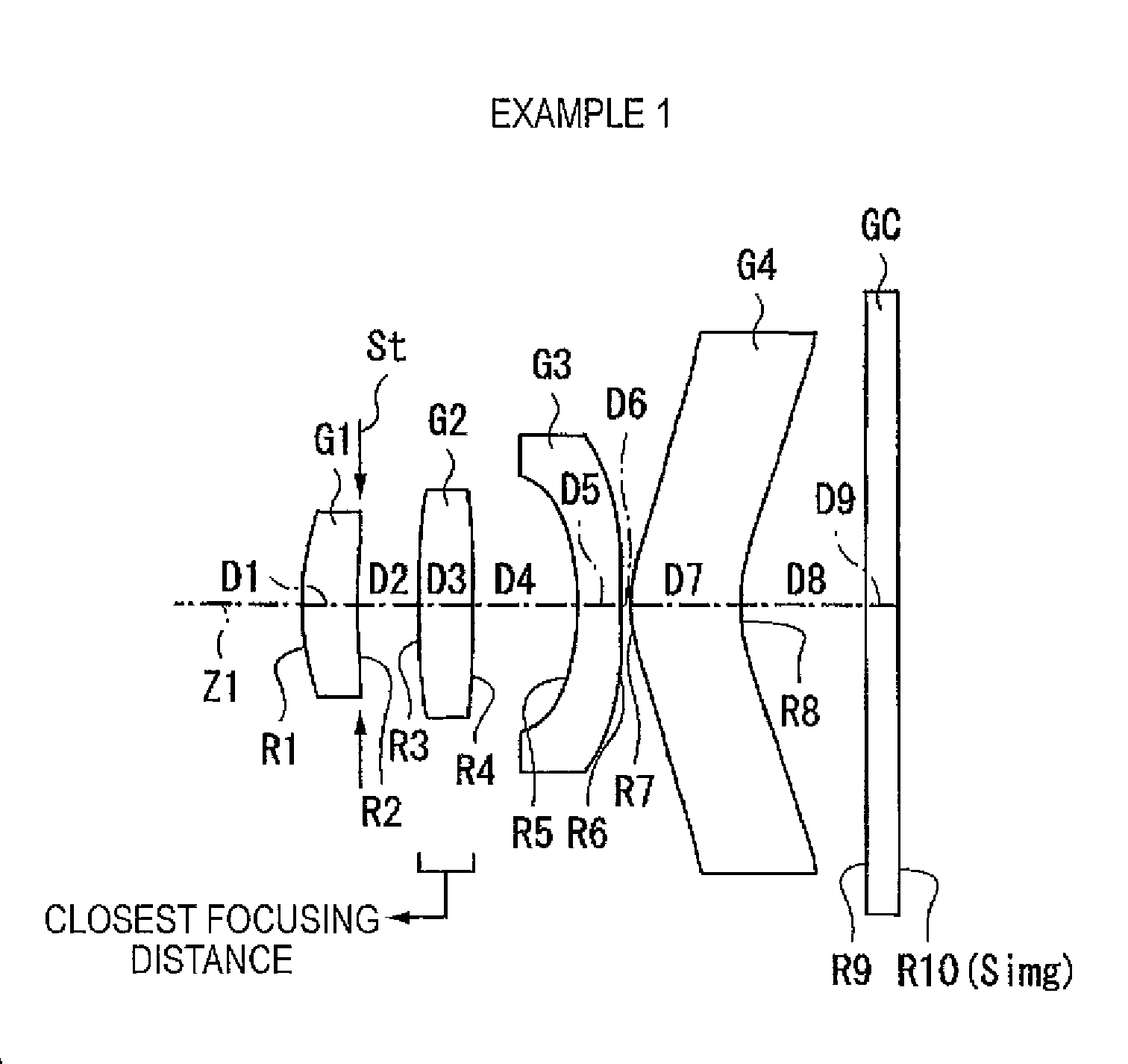
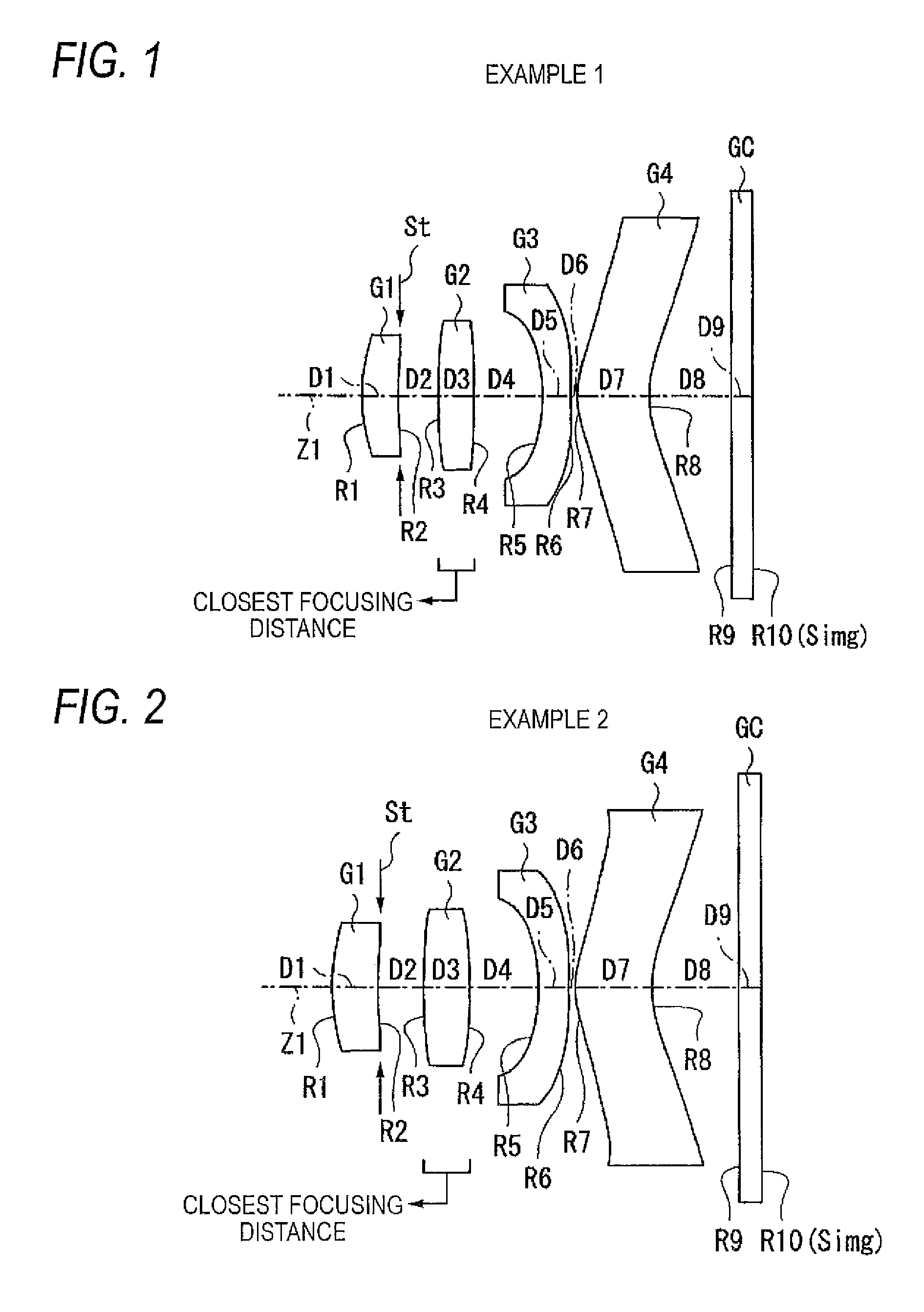
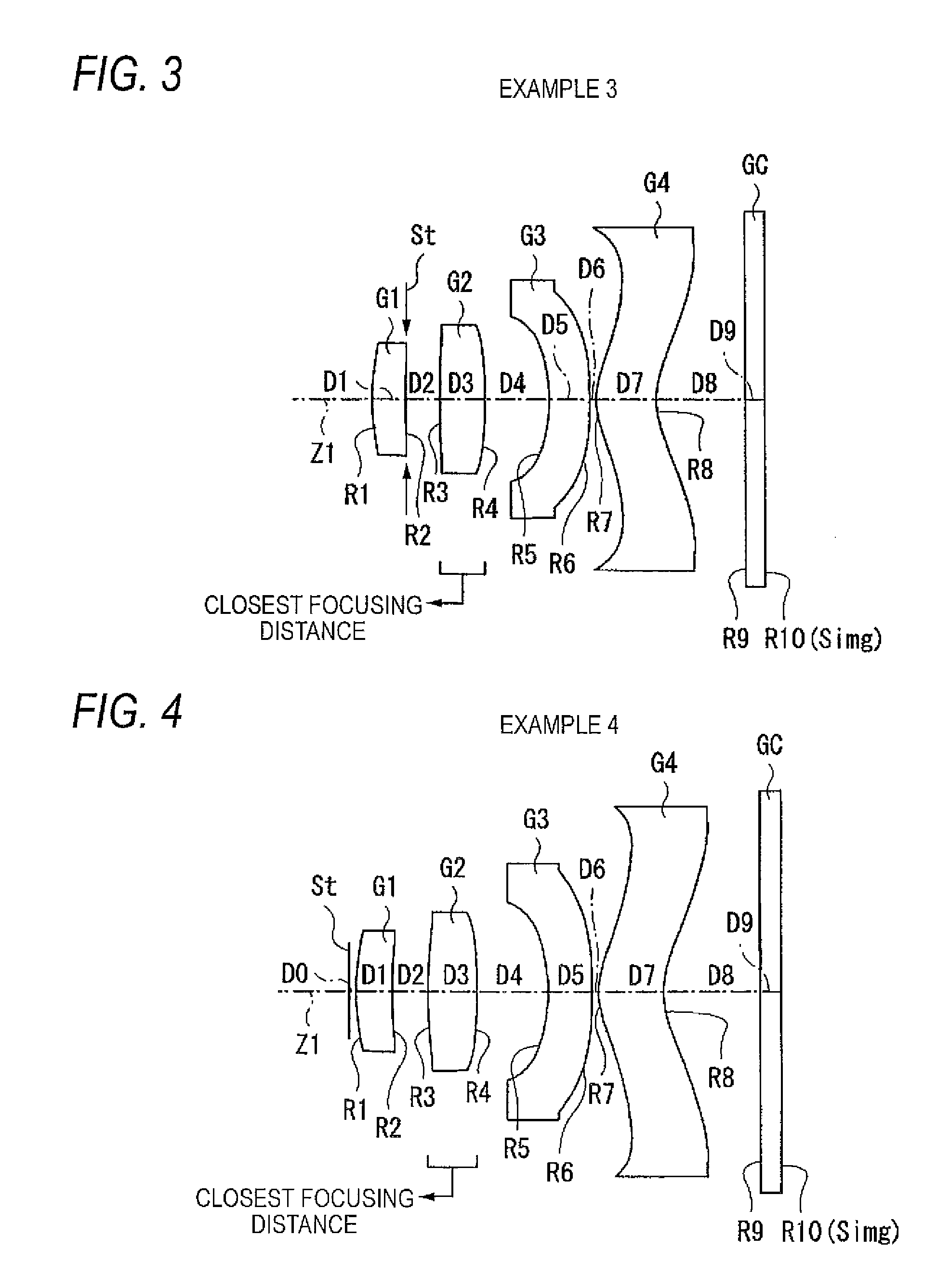
[0080]Specific lens data which correspond to the configuration of the imaging lens shown in FIG. 1 are shown in FIGS. 6A and 6B as Example 1. In particular, FIG. 6A shows lens data of Example 1, and FIG. 6B shows data in relation to aspheric surfaces. Shown in a surface number Si column in the lens data shown in FIG. 6A is a surface number of an ith (i=1 to 10) surface which results when giving reference alphanumerics to surfaces of the constituent lenses in the increasing order from an object side towards an image side with an object side surface of a first lens from the object side regarded as a first surface. Shown in a column of radius of curvature Ri is a value (mm) of a radius of curvature of the ith surface from the object side in such a manner as to correspond to the reference alphanumeric Ri given ...


PUM


Abstract

A single focus imaging lens comprises: a front lens group including one or two lenses and having a positive refractive power as a whole; a rear lens group including two or three lenses and having a negative refractive power as a whole; and a focusing lens, disposed between the front lens group and the rear lens group, that has a positive refractive power and moves on an optical axis for adjusting focus, wherein the following conditional expression is satisfied:1.0<FL / f<5.0  (X)wheref: focal length of the single focus imaging lens;FL: focal length of the focusing lens.

Description

BACKGROUND OF THE INVENTION[0001]1. Field of the Invention[0002]The present invention relates to an imaging lens which is to be installed in an image pick-up apparatus such as a digital still camera, a mobile phone with a camera, and a personal digital assistants (PDA) which utilizes an image sensing device such as a CCD (Charge Coupled Device) or a CMOS (Complementary Metal Oxide Semiconductor) and more particularly to a single focus imaging lens which can adjust focus.[0003]2. Description of the Related Art[0004]In recent years, miniaturization and increase in the number of pixels mounted have been in progress in image sensing devices such as CCDs and CMOSes. In conjunction with this trend, smaller and higher-performance image pick-up equipment and lenses installed thereon have been in demand. In the related art, many of imaging lenses to be installed on, for example, mobile phones with a camera are made up of three lenses. However, in order to cope with the increase in the number...

Claims


Application Information

Patent Timeline
Patent Type & Authority Patents(United States)
IPC IPC(8): G02B9/34
CPCG02B13/004G02B9/34G02B9/60G02B3/00
Inventor SATO, KENICHI
Owner TIANJIN OFILM OPTO ELECTRONICS CO LTD
Why Eureka
Try Eureka