Supercharge Your Innovation With Domain-Expert AI Agents!

Digital imaging method and apparatus for mammography

a digital imaging and mammography technology, applied in the field of digital imaging methods, can solve the problems of large sensor area and therefore high cost, difficult to approve curved compression surfaces for many people to begin, and difficult to achieve the approval of many people's initial curved surfaces

Inactive Publication Date: 2009-09-15
PLANMED OY
View PDF16 Cites 1 Cited by
  • Summary
  • Abstract
  • Description
  • Claims
  • Application Information

AI Technical Summary

Benefits of technology

[0014]The essential features of the invention are expressed more precisely in the attached claims. These features include that when during the imaging scan the sensor surface is kept continuously at right ang

Problems solved by technology

A clear disadvantage of this technology is the need for sensors that are large in area and thus very expensive, and on the other hand the need to take into account the secondary radiation scattering from the object being imaged, which requires e.g. arranging complex mechanical grid structures in front of the detector.
However, such a solution is considerably more economical in total costs than solutions based on a full field sensor, especially due to its smaller sensor area.
Although it is in principle mechanically simple to keep the sensor arrangement at right angles to the beam according to the solution of the above-mentioned publication, use of it also causes certain problems.
For example, as it has been customary in mammography to position and compress the object to be imaged motionless between plane-like compression paddles, the curved compression surfaces are difficult to approve for many people to begin with.
Practical problems may also occur, especially when small breasts are being positioned between wide curved surfaces.
Additionally, such a way of positioning the object causes the imaging geometry becoming different compared to the traditional one, which geometry is further affected differently by the thickness of the tissue to be imaged than in the traditional solution.
Furthermore, when using curved surfaces, typical special imaging modes used in mammography, such as enlargement, spot and stereotaxic imaging must be implemented in a completely new way, in which case they require specific solutions of their own, and all the traditional imaging modes are not even realizable in connection with such a solution—at least not without completely new special arrangements.

Method used


Image

  • Digital imaging method and apparatus for mammography
  • Digital imaging method and apparatus for mammography
  • Digital imaging method and apparatus for mammography

Examples


Embodiment Construction

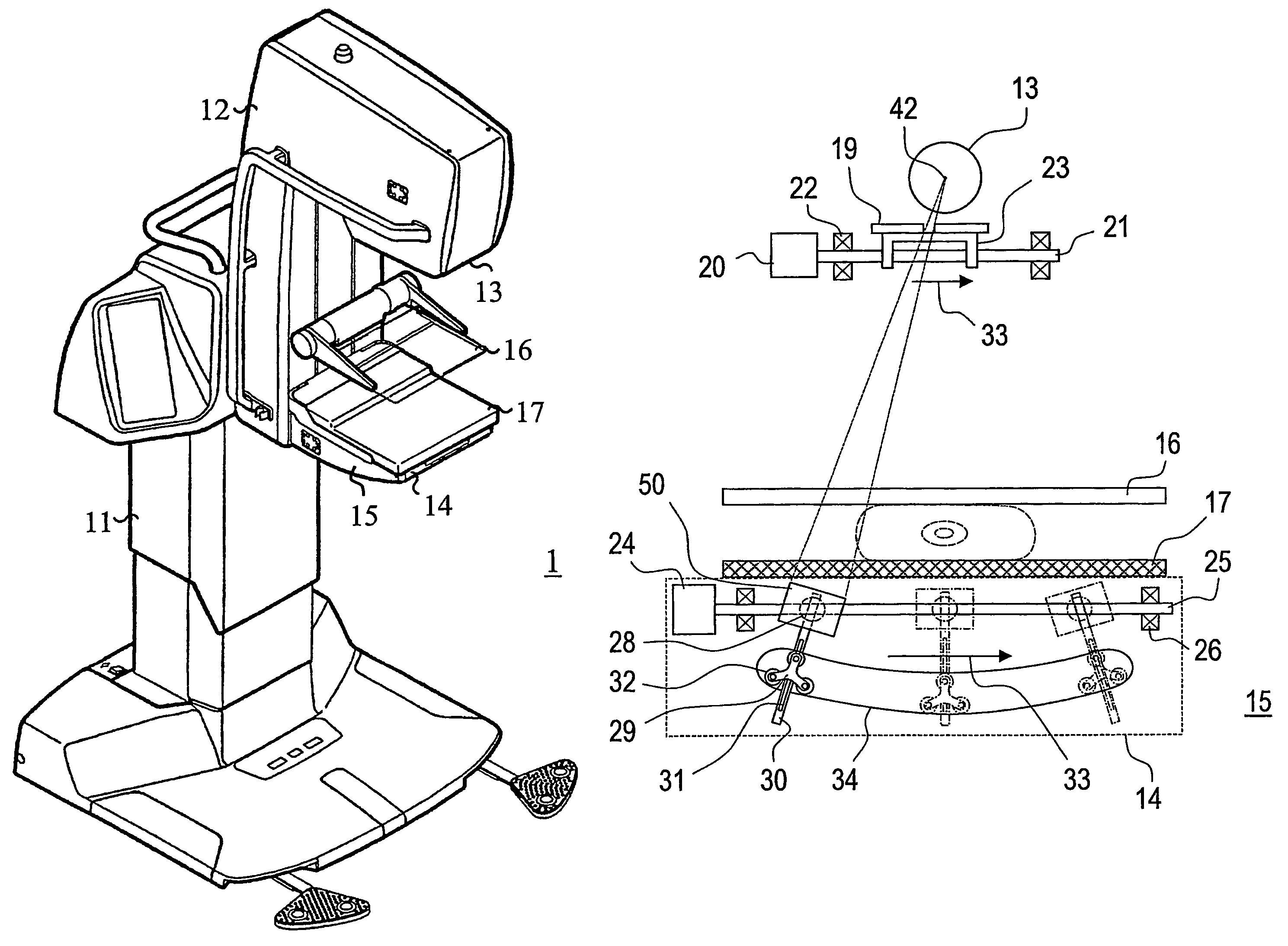
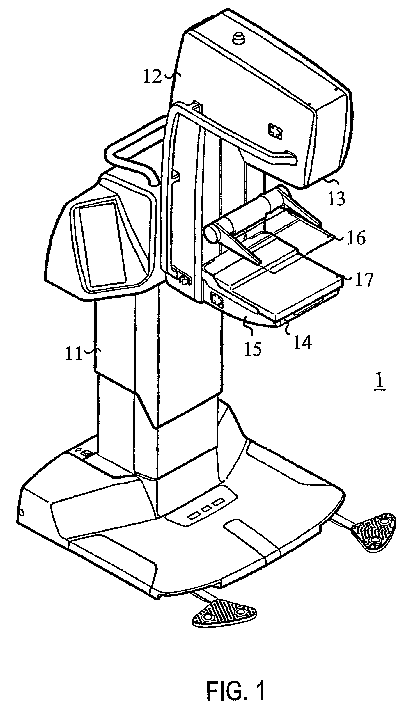
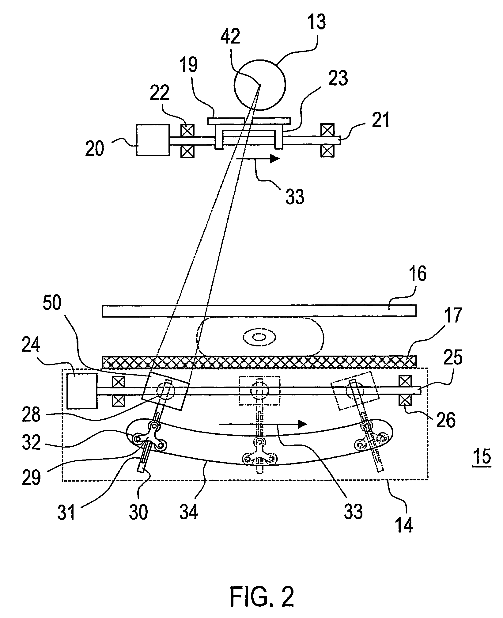
[0020]The mammography apparatus 1 presented in FIG. 1 consists of a body part 11 and a C-arm 12 connected to it. Typically a radiation source 13 and, e.g. inside the lower shelf 14, image data receiving means 15 are placed on the opposite ends of the C-arm 12, which imaging means 13, 15 when being situated inside the cover of the apparatus are not actually visible in FIG. 1. Additionally, means 16, 17 for positioning the object to be imaged within the imaging area are located within the area between these imaging means 13, 15, typically near the image data receiving means 15. Typically, the C-arm 12 is movable both in vertical direction in relation to means 16, 17 for positioning the object to be imaged and rotatable in relation to the body part 11. The positioning means 16, 17 are typically formed of an upper compression paddle 16 and a lower compression paddle 17, which lower compression paddle 17 may be arranged to function as a so called bucky as well. Bucky means a grid structu...


PUM


Abstract

A digital imaging apparatus and method which includes a radiation source and a sensor arrangement for detecting radiation. The sensor arrangement contains one or more sensors formed of one or more preferably elongated sensor modules, which sensor module contains one or more pixel columns which receive image data. The digital imaging apparatus includes means for positioning the object to be Imaged which is situated within the area between the radiation source and the sensor arrangement, and means for limiting the beam from the radiation source essentially according to the active sensor surface of the said sensor arrangement. Also included is means to move the beam across the object being positioned to be imaged and means to move the at least one sensor belonging to the sensor arrangement in synch with the scanning movement of the beam in order to keep the active sensor surface essentially at right angles to the beam on the plane formed by the scanning movement.

Description

BACKGROUND OF THE INVENTION[0001]The present invention relates generally to imaging of an object by electromagnetic radiation, especially to digital mammography.[0002]1. Field of the Invention[0003]More precisely, the invention relates to a digital imaging method in which the radiation that has passed through the object to be imaged is detected on at least one sensor, which contains one or more preferably elongated sensor modules, wherein the said sensor module contains one or more pixel columns which receive image data, in which method the object to be imaged is arranged essentially motionless and is scanned across with a beam which originates from a radiation source, the focus of which being essentially motionless in space, the beam being limited to be narrower than the object to be imaged and adapted essentially to the active surface of the sensor, and in which method the sensor is moved in synch with the scanning movement of the beam while at the same time the said active surfac...

Claims


Application Information

Patent Timeline
IPC IPC(8): A61B6/04G21K5/10H01J31/49A61B6/00
CPCA61B6/502
Inventor STROMMER, PEKKASULIN-SAARISTO, TIMOVIRTA, ARTO
Owner PLANMED OY
Features
  • R&D
  • Intellectual Property
  • Life Sciences
  • Materials
  • Tech Scout
  • Unparalleled Data Quality
  • Higher Quality Content
  • 60% Fewer Hallucinations
Learn More