
Bidirectional pivot structure

a bi-directional pivot and structure technology, applied in the direction of hinges, manufacturing tools, television systems, etc., can solve the problems of high difficulty in reducing volume and high manufacture cost, and achieve the effect of effectively minimizing the volume of the bi-directional pivot structur

Inactive Publication Date: 2009-09-22
CHENMING MOLD IND CORP
View PDF9 Cites 6 Cited by
  • Summary
  • Abstract
  • Description
  • Claims
  • Application Information

AI Technical Summary

Benefits of technology

"The present invention provides a bidirectional pivot structure that can rotate in both horizontal and vertical directions. The structure includes a horizontal rotation axis module, a rotation switching device, and a vertical rotation axis module. The vertical rotation axis module includes an aligning element, a rotation position limiting element, a stabilizing element, a flexible element, and a locking element. The rotation switching device includes at least one wedging portion and at least one fixing portion. The alignment element, guide element, positioning element, and fixing element are made of wear-resisting metal material. The flexible element is composed of a resilient plate and can further include at least one fourth fixing protrusion. The present invention achieves the effect of positioning and limiting the vertical rotation axis module, and effectively minimizes the volume of the bidirectional pivot structure."

Problems solved by technology

However, as to the simplification of components and the convenience of the assembly (as shown in the drawings of the patent application), if such pivot device is applied in a digital camera, then the its volume must be reduced significantly, and the concatenate rotation axis in vertical direction requires lots of components and a complicated assembly procedure, and it causes a much higher manufacture cost, and a higher level of difficulty to reduce the volume that awaits for further improvement.

Method used


Image

  • Bidirectional pivot structure
  • Bidirectional pivot structure
  • Bidirectional pivot structure

Examples


Embodiment Construction

[0023]The present invention relates to a bidirectional pivot structure. While the specifications describe at least one embodiment of the invention considered best modes of practicing the invention, it should be understood that the invention can be implemented in many ways and is not limited to the particular examples described below or to the particular manner in which any features of such examples are implemented.

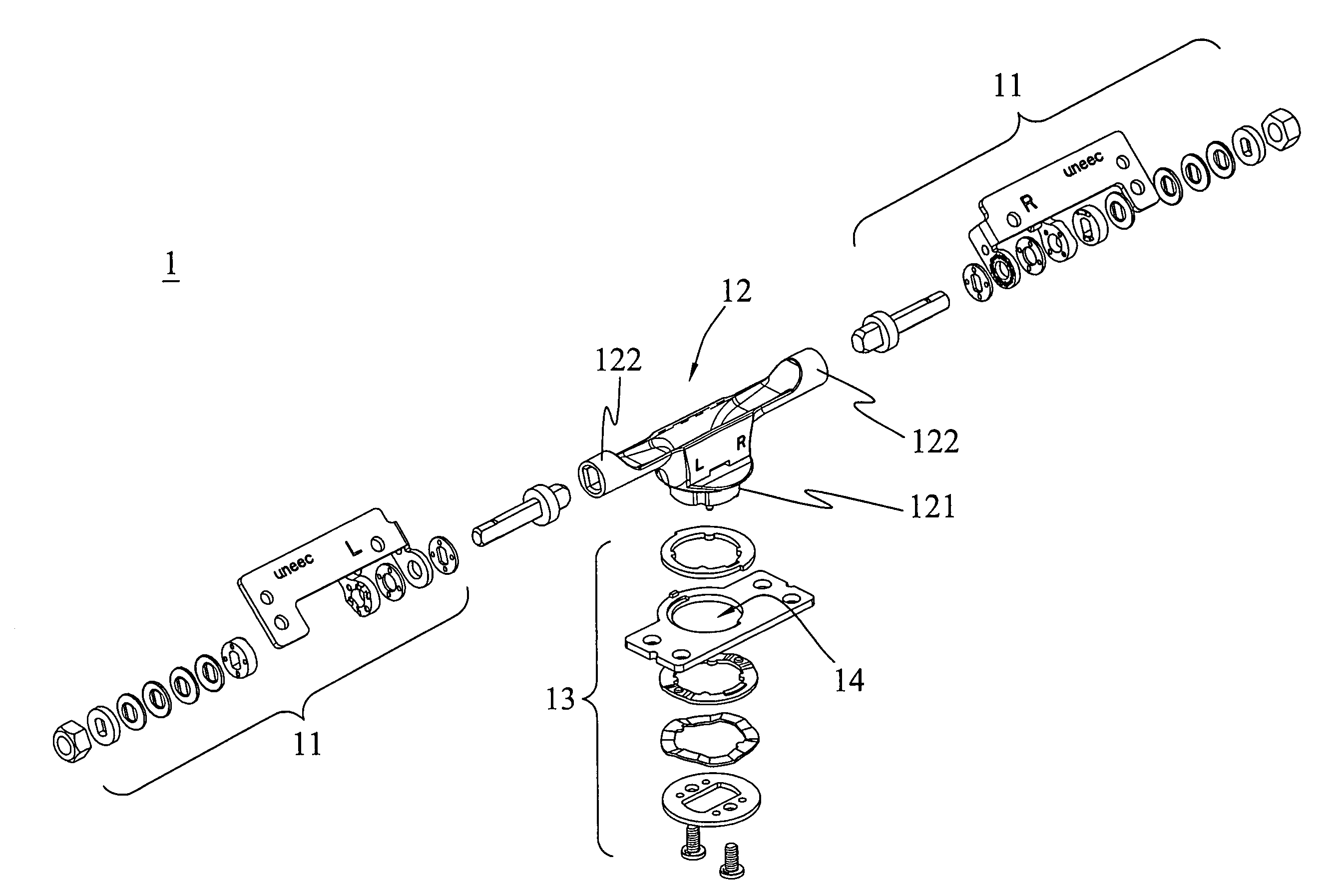
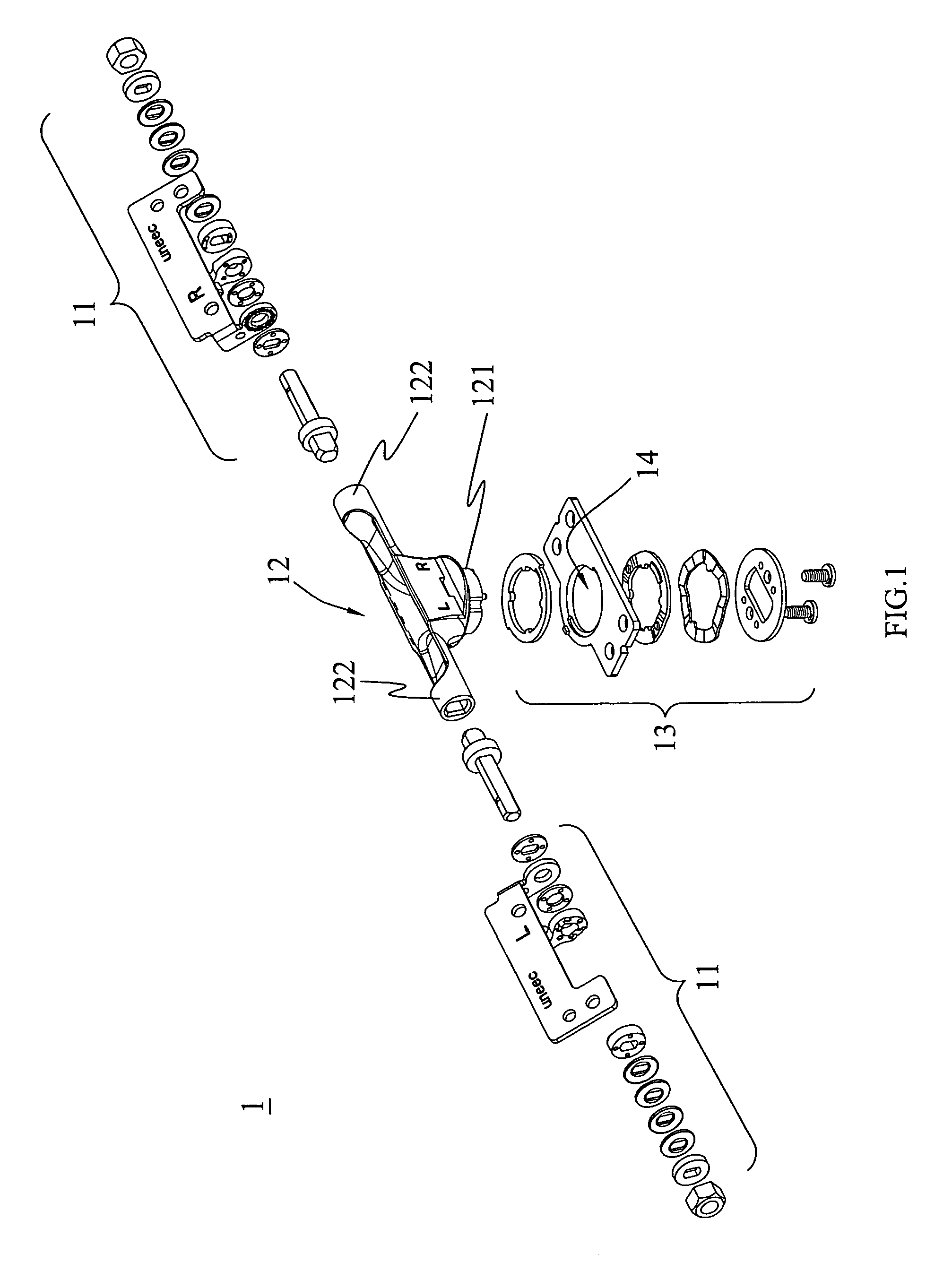
[0024]Referring to FIG. 1 for an exploded view of a bidirectional pivot structure of the present invention, the bidirectional pivot structure 1 comprises at least one horizontal rotation axis module 11, a rotation switching device 12 and a vertical rotation axis module 13. The rotation switching device 12 includes at least one wedging portion 121 and at least one fixing portion 122 pivotally connected to the horizontal rotation axis module 11, and the vertical rotation axis module 13 includes a hole 14 for fitting the rotation switching device 12.

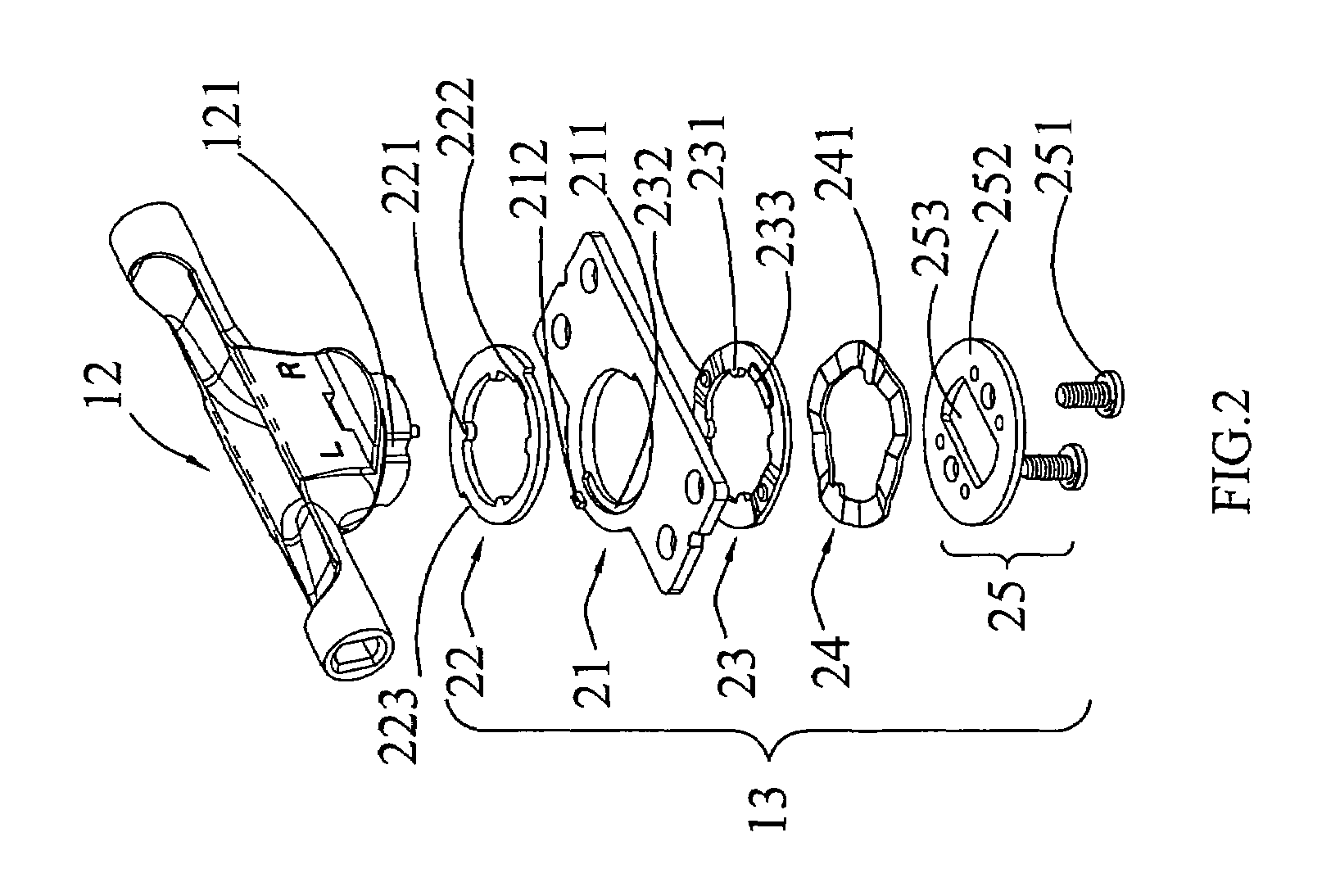
[0025]Referring to FIG. 2 ...


PUM


Abstract

A bidirectional pivot structure includes a horizontal rotation axis module, a rotation switching device and a vertical rotation axis module. The rotation switching device is pivotally connected to the horizontal rotation axis module and the vertical rotation axis module. The vertical rotation axis module includes an aligning element, a rotation position limiting element, a stabilizing element, a flexible element and a locking element. The rotation position limiting element has a position limiting convex dot and a position limiting arc fitted to a guide rail and a position limiting protrusion of the aligning element for limiting the rotary angle of the vertical rotation axis module. The stabilizing element has a positioning convex dot and a stabilizing protrusion fitted to the positioning holes of the aligning element to maintain a frictional stability. By the design of the aligning element, rotation position limiting element and stabilizing element, the effect of limiting and positioning the vertical rotation axis module can be achieved.

Description

BACKGROUND OF THE INVENTION[0001]1. Field of the Invention[0002]The present invention relates to a bidirectional pivot structure, and more particularly to a bidirectional pivot structure with a function of rotating in both horizontal and vertical directions.[0003]2. Description of the Related Art[0004]Generally, in design of the consuming electronic products having a flip-cover, such as a portable computer, a mobile phone, an electronic dictionary, a portable multimedia player, a digital image capturing device, such as a digital camera or an automobile display, the main body is disposed at a side of the product and pivotally connected with the cover portion by a rotation axis, so that the cover portion can be opened or closed relative to the main body. Therefore, the rotation axis is a major factor for determining the quality of the product. In fact, a good rotation axis not only has necessarily good holding effect, but also is designed with simple elements and convenient assembly, ...

Claims


Application Information

Patent Timeline
Patent Type & Authority Patents(United States)
IPC IPC(8): E05D3/10
CPCH04N5/64H04N5/782E05D3/10Y10T16/547Y10T16/551Y10T16/5472
Inventor CHANG, YANG CHIHYANG, CHIH-CHIEH
Owner CHENMING MOLD IND CORP
Learn More