Vacuum booster of brake device

a technology of vacuum booster and brake device, which is applied in the direction of fluid coupling, rotary clutch, servomotor, etc., can solve the problems of generating vibration or noise, reducing the area of the valve mechanism, and preventing vibration and noise in the valve mechanism

Inactive Publication Date: 2009-09-22
ADVICS CO LTD
View PDF7 Cites 0 Cited by
  • Summary
  • Abstract
  • Description
  • Claims
  • Application Information

AI Technical Summary

Benefits of technology

[0014]Accordingly, it is a primary object of the present invention to provide a vacuum booster of brake device, which is constructed such that, when the temperature is low, an area is reduced, with which a port communicating with a reservoir and being open to a master cylinder communicates with the master cylinder, so that sufficient reaction force is transmitted from a piston of the master cylinder to a valve mechanism, thus preventing vibration and noise in the valve mechanism.
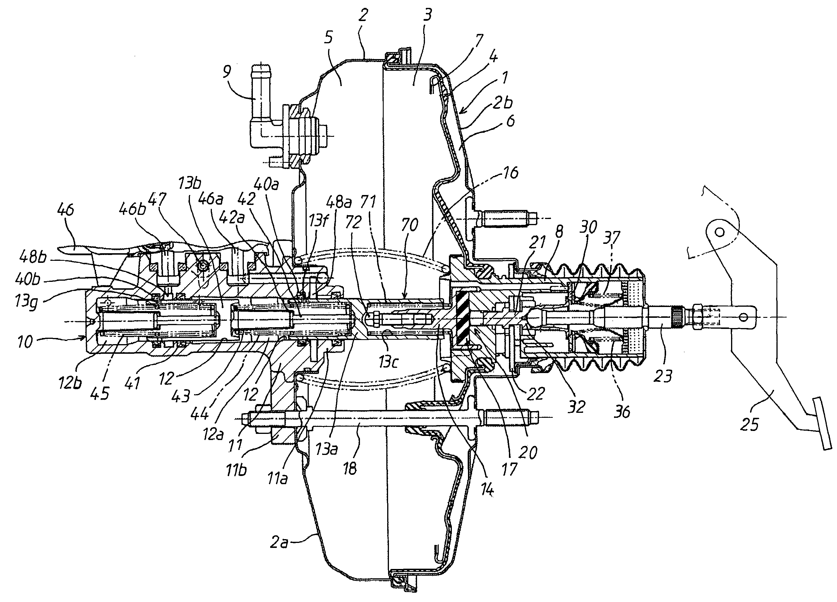
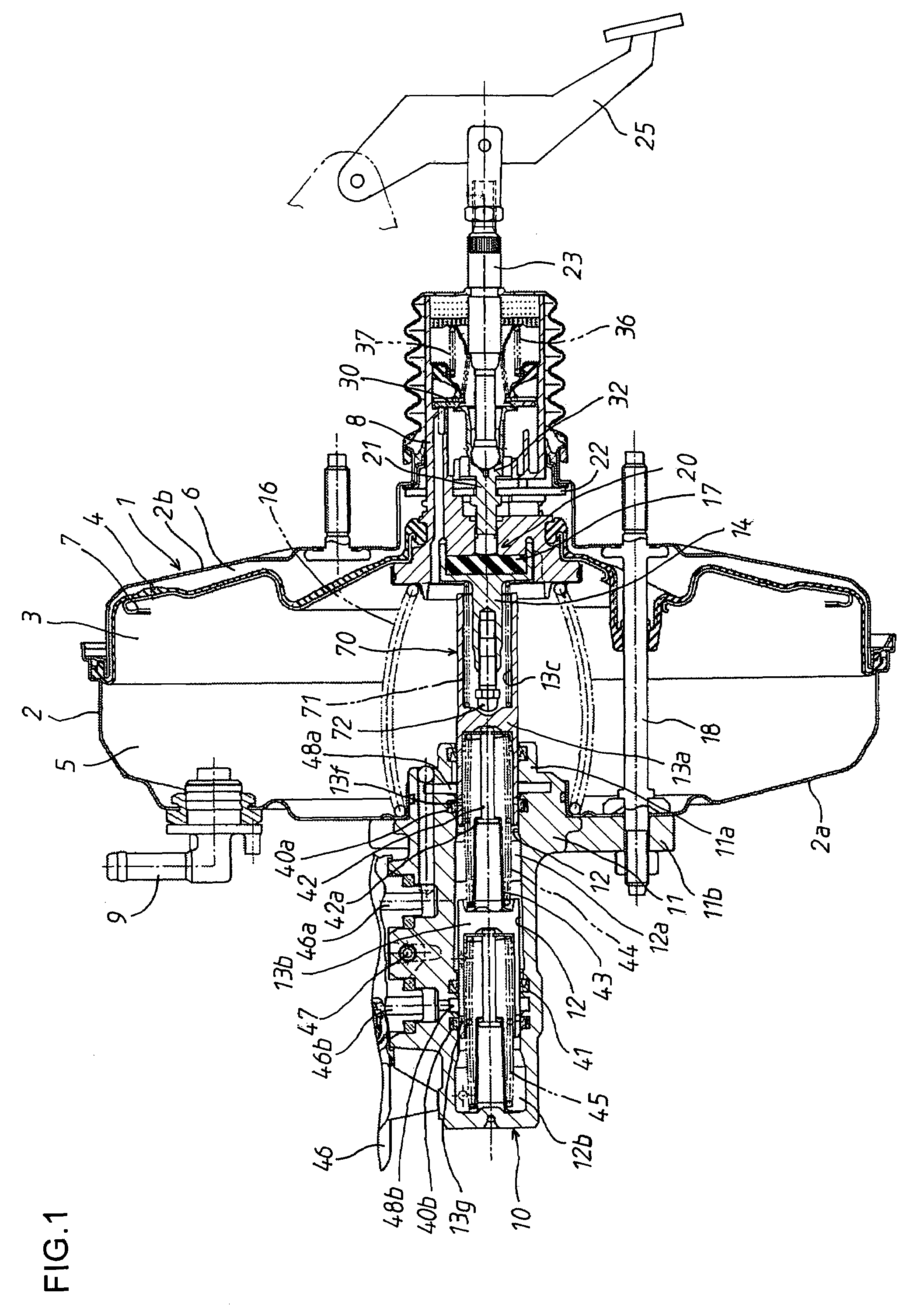
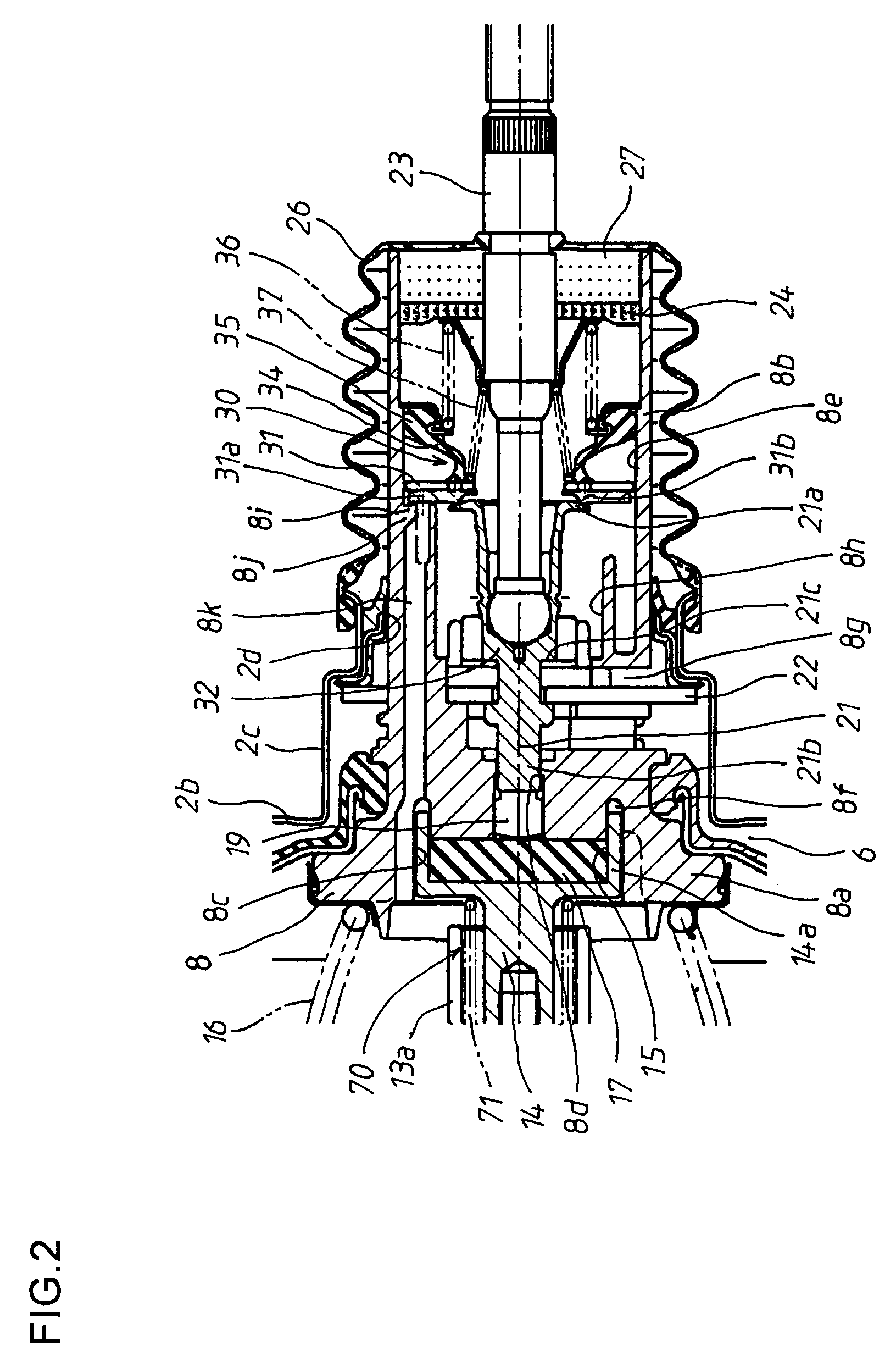
[0015]Briefly, according to the present invention, there is provided a vacuum booster of a brake device comprising a master cylinder having a piston slidably fitted in a cylinder having a port communicating with a reservoir, so that the port is closed by forward movement of the piston to transmit liquid pressure from the cylinder; the vacuum booster to boost a force for operating a brake to push and move the piston; a wheel cylinder supplied with the liquid pressure from the master cylinder to operate a braking unit of each of the wheels; and an liquid pressure generating unit to pump and supply brake liquid stored in the reservoir to the wheel cylinder through the port by using a pump, in which the vacuum booster comprises: a booster shell defining a pressure chamber therein; a partition member provided in the booster shell so as to be movable forwards and backwards, and partitioning the pressure chamber into a variable pressure chamber and a negative pressure chamber; a valve piston coupled to the partition member; an input member provided in the valve piston so as to be movable forwards and backwards relative to the valve piston; a valve mechanism including an atmospheric valve seat and a negative pressure valve seat respectively provided in the input member and the valve piston, an atmospheric valve removably contacting the atmospheric valve seat to communicate or isolate the variable pressure chamber with or from an atmosphere, and a negative pressure valve removably contacting the negative pressure valve seat to communicate or isolate the variable pressure chamber with or from the negative pressure chamber; an output member provided in the valve piston so as to be movable forwards and backwards relative to the valve piston, which pushes and moves the piston with forward movement of the valve piston; reaction applying means for transmitting part of reaction force that is transmitted from the piston to the output member to the input member; and stop position shifting means for shifting a stop position of the piston, at which the piston is prevented from being moved backwards by the output member when the valve piston is at a non-operating position, such that the stop position of the piston at high temperature is set ahead of the stop position at low temperature, thus reducing an area with which the port and the cylinder communicate with each other.
[0016]With this construction, when the temperature is low, while the valve piston is at a non-operating position, the stop position, at which the piston of the master cylinder is prevented from being moved further backwards by the output rod, is shifted forwards by the stop position shifting means, thus reducing the area with which the port communicating with the reservoir and being open to the cylinder communicates with the cylinder. Thereby, when the piston is pushed and moved forwards by the output member of the vacuum booster, the port is immediately isolated from the cylinder, so that the generation of liquid pressure in the cylinder begins at the initial stage of the braking operation, thus the reaction force is transmitted from the piston to the output rod, thereby preventing vibration or noise in the valve mechanism.
[0017]Meanwhile, when the temperature is low, while the valve piston is at the non-operating position, the stop position of the piston is not shifted forwards, so that the area with which the port communicates with the cylinder is increased and maintained wide. Therefore, when the master cylinder is in the non-operating state, the liquid pressure generating unit is able to pump brake liquid from the reservoir through the port by using the pump to rapidly supply it to the wheel cylinder. Furthermore, because the viscosity of the brake liquid is low when the temperature is low, even though the piston is not moved forward by the output rod of the vacuum booster and communication between the port and the cylinder is maintained, the generation of liquid pressure in the cylinder begins at the initial stage of the braking operation, and the reaction force is transmitted from the piston to the output rod, thus preventing vibration or noise in the valve mechanism.

Problems solved by technology

However, the conventional vacuum booster is problematic in that, at the initial stage of the braking operation, as the reaction force is small, and the servo balance of the valve mechanism, in which the negative pressure valve and the atmospheric valve are closed together, is unstable, vibration or noise is generated.
In other words, when the reaction force from the piston is small, the force applied in the direction in which the atmospheric valve is closed is small, and therefore the atmospheric valve is not reliably closed, so that outside air is drawn too much into the variable pressure chamber.
It results in generating vibration.
However, in such a construction, because liquid pressure is not applied to the wheel cylinder until the port is isolated from the master cylinder by the piston that is pushed and moved forwards by the output member of the vacuum booster when the master cylinder is operated, reaction force from the piston is reduced at the initial stage of the braking operation, with the result that the valve mechanism easily vibrates.
However, because the flow rate of air is restricted by contraction, it is necessary to greatly increase contraction resistance to prevent vibration and noise in the valve mechanism.
As a result, at the initial stage of the braking operation of the vacuum booster, operational responsiveness is deteriorated.

Method used


Image

  • Vacuum booster of brake device
  • Vacuum booster of brake device
  • Vacuum booster of brake device

Examples


second embodiment

[0063]As shown in FIG. 5, in the stop position shifting means 70, an axial hole 13c is axially formed in the rear end of the first piston 13a. A stepped hole 13d is formed in the bottom of the axial hole 13c. A contact shaft part 73a provided on the front end of a contact member 73 is slidably fitted in a small-diameter hole 13e of the stepped hole 13d. A compression spring 71, which is an elastic member made of a shape memory alloy, is interposed between the back surface of a head part 73b of the contact member 73 and the stepped portion of the stepped hole 13d. The head part 73b of the contact member 73 faces a rod part 14b, which extends forwards from the output rod 14.

[0064]When the temperature is high, the compression spring 71 is returned to the memorized shape. Therefore, when the valve piston 8 and the output rod 14 are at non-operating positions, the stop position of the first piston 13a, at which the first piston 13a is prevented from being moved further backwards by the o...

third embodiment

[0066]As shown in FIG. 6, in the stop position shifting means 70, the output rod 14 is divided into a first output part 14c and a second output part 14d. The first output part 14c includes a ring-shaped protrusion 14a, which is fitted in the ring-shaped groove 8f of the valve piston 8. The second output part 14d includes a rod part 14b, which contacts the first piston 13a. In addition, a stepped hole 14e is formed in the rear end of the second output part 14d. A contact shaft part 14g provided on the back surface of the first output part 14c is slidably fitted in a small-diameter hole 14f of the stepped hole 14e. A compression spring 71, which is an elastic member made of a shape memory alloy, is interposed between a stepped portion of the stepped hole 14e and the back surface of the first output part 14c.

[0067]When the temperature is low, the compression spring 71 is returned to the memorized shape. Therefore, while the valve piston 8 is at a non-operating position, the second out...

fourth embodiment

[0069]As shown in FIG. 7, in the stop position shifting means 70, a compression spring 71, which is an elastic member made of a shape memory alloy, is interposed between the inner surface of the protruding part 2c of the rear booster shell 2b and the key member 22, which radially passes through the valve piston 8 and contacts the inner surface of the protruding part 2c to limit backward movement of the valve piston 8 and the input member 32 relative to the booster shell 2. Thus, when the temperature is high, the position at which the backward movement of the key member 22 is limited, is set ahead compared to when the temperature is low.

[0070]When the temperature is high, the compression spring 71 is returned to the memorized shape. Therefore, when the valve piston 8 is at a non-operating position, the key member 22 contacts the compression spring 71 abutting to the inner surface of the protruding part 2c, and thereby the key member 22 is stopped at the stop position shifted forwards...


PUM


Abstract

The present invention provides a vacuum booster, which is constructed such that an area with which a cylinder communicates with a port communicating with a reservoir and being open to the cylinder is reduced at high temperature, so that a sufficient reaction force can be transmitted from a piston of a master cylinder to a valve mechanism at an initial stage of the braking operation, thus preventing vibration or noise from being generated in the valve mechanism. At high temperature, stop position, at which backward movement of the piston of the master cylinder is limited by an output member while a valve piston is at a non-operating position, is shifted forwards by a stop position shifting means, thus reducing the area with which the cylinder communicates with the port communicating with the reservoir and being open to the cylinder. At low temperature, while the valve piston is at the non-operating position, the stop position of the piston is not shifted, thus maintaining the area wide, with which the port communicates with the cylinder.

Description

INCORPORATION BY REFERENCE[0001]This application is based on and claims priority under 35 U.S.C. sctn. 119 with respect to Japanese Application No. 2006-141420 filed on May 22, 2006, the entire content of which is incorporated herein by reference.BACKGROUND OF THE INVENTION[0002]1. Field of the Invention[0003]The present invention relates generally to vacuum boosters for vehicles. More particularly, the present invention relates to a vacuum booster of brake device, which is adapted for a brake device including an liquid pressure generating unit pumping and supplying brake liquid stored in a reservoir to a wheel cylinder by using a pump through a port that is open to a cylinder of a master cylinder.[0004]2. Discussion of the Related Art[0005]As well known to those skilled in the art, a typical vacuum booster includes a partition member, which is installed in a booster shell so as to be movable forwards and backwards to partition a pressure chamber into a variable pressure chamber and...

Claims


Application Information

Patent Timeline
Patent Type & Authority Patents(United States)
IPC IPC(8): B60T13/56F15B9/10
CPCB60T8/38B60T13/569B60T8/4872
Inventor INOUE, YOJIYASUI, YOSHIYUKI
Owner ADVICS CO LTD
Why Eureka
Try Eureka