Compressed cartridge heater

a heater and cartridge technology, applied in the field of compressed cartridge heaters, can solve the problems of high manufacturing cost and difficulty in filling, and achieve the effect of manufacturing with minimal effort in terms of labor and material

Active Publication Date: 2009-09-22
TUERK HILLINGER
View PDF17 Cites 25 Cited by
  • Summary
  • Abstract
  • Description
  • Claims
  • Application Information

AI Technical Summary

Benefits of technology

[0007]The basic object of the present invention is to create a compressed cartridge heater of the type mentioned in the introduction, which can be manufactured with minimal effort in terms of labor and material.
[0009]Due to the arrangement according to the present invention and the provision of flat insulating plates as the carrier for the heating coil, it is substantially simpler to place heating coils within the tube such that they cannot come into contact with the wall of the tube, so that less care is needed when filling in the insulating granular material, and this filling in can be carried out substantially more rapidly and thus at a lower cost. The connecting coil section may consist of a short wire section or comprise one or more windings.
[0011]Another simple possibility of insulating the coil section led around this lower end edge against the bottom of the tubular body and of keeping it away from it is the deflecting edge being formed by the narrow-side end edge of the insulating plate and the coil section led around same being separated from the bottom of the tubular body by an insulating disk or a spacer ring.
[0014]The holding clamps may be provided with clamping fingers, which mesh with said locking notches of the insulating plate. The holding clamps may comprise U-shaped flat bodies and have U-shaped recesses in which the heating coils (8, 9) are guided. These measures guarantee simple and reliable fastening of the holding clamps on the insulating plate and, moreover, sufficient fixation in space of the heating coils within the tubular body.
[0016]Another advantageous embodiment of the cartridge heater according to the present invention presents the special advantages that the heating coils extending in parallel next to one another are mutually insulated by the insulating plates located in between.
[0018]Holding clamps, which prevent the individual heating coil strands from bending out radially, may be provided in case of greater overall length.

Problems solved by technology

No support elements, which ensure that when the insulating granular material is filled in, the windings of the heating coil will not come into contact with the tube wall, are provided whatsoever for the heating coils within the metal tube in these prior-art cartridge heaters.
This makes it difficult to fill in the granular material and causes high manufacturing costs.

Method used


Image

  • Compressed cartridge heater
  • Compressed cartridge heater
  • Compressed cartridge heater

Examples


Embodiment Construction

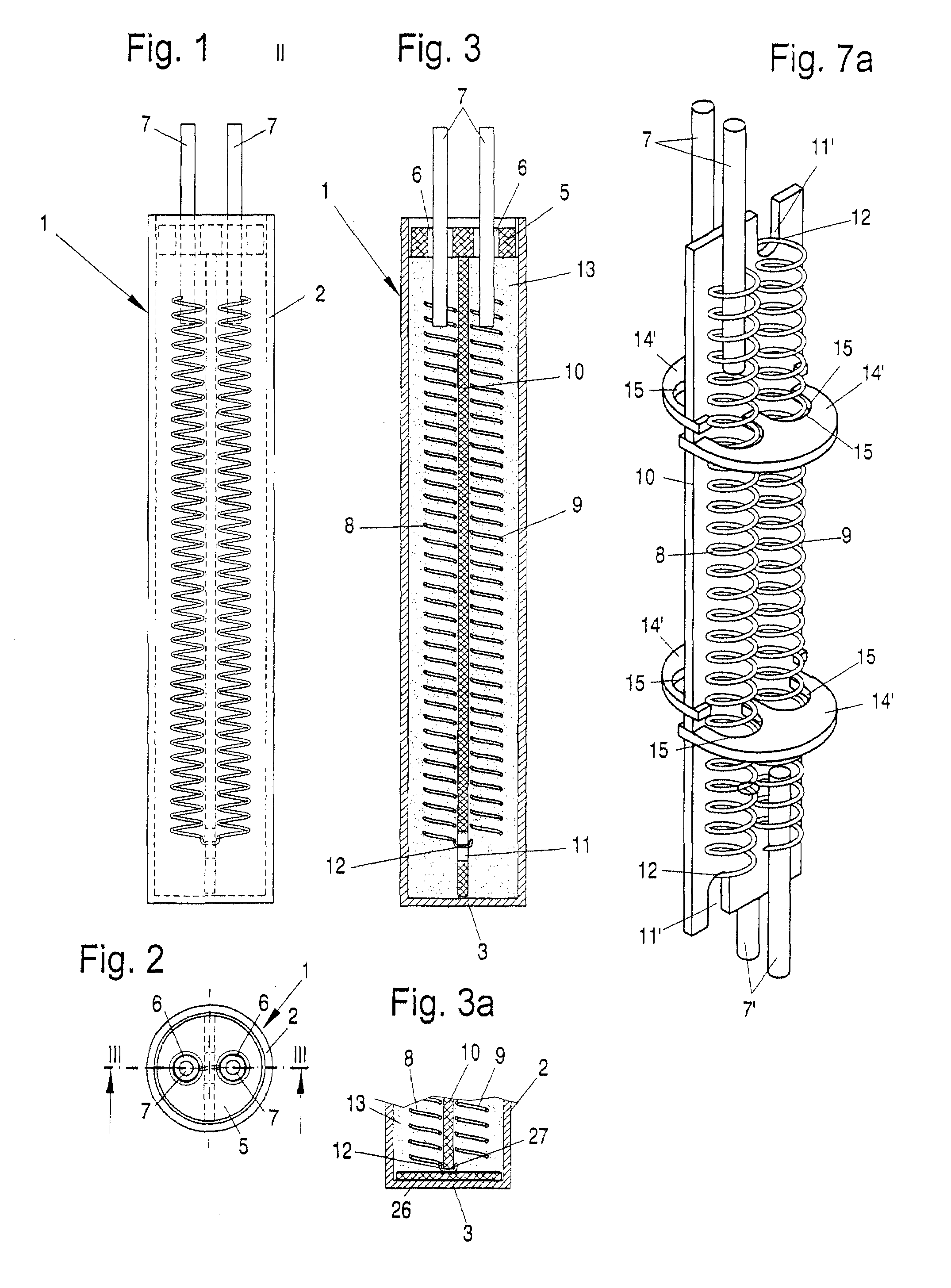
[0048]Referring to the drawings in particular, the cartridge heater 1 comprises a cylindrical tubular body 2, which has a fixed bottom 3 and whose upper, open end 4 is closed by a closing disk 5. The tubular body 2 consists of metal, preferably stainless steel. It may also consist of brass, copper or the like.

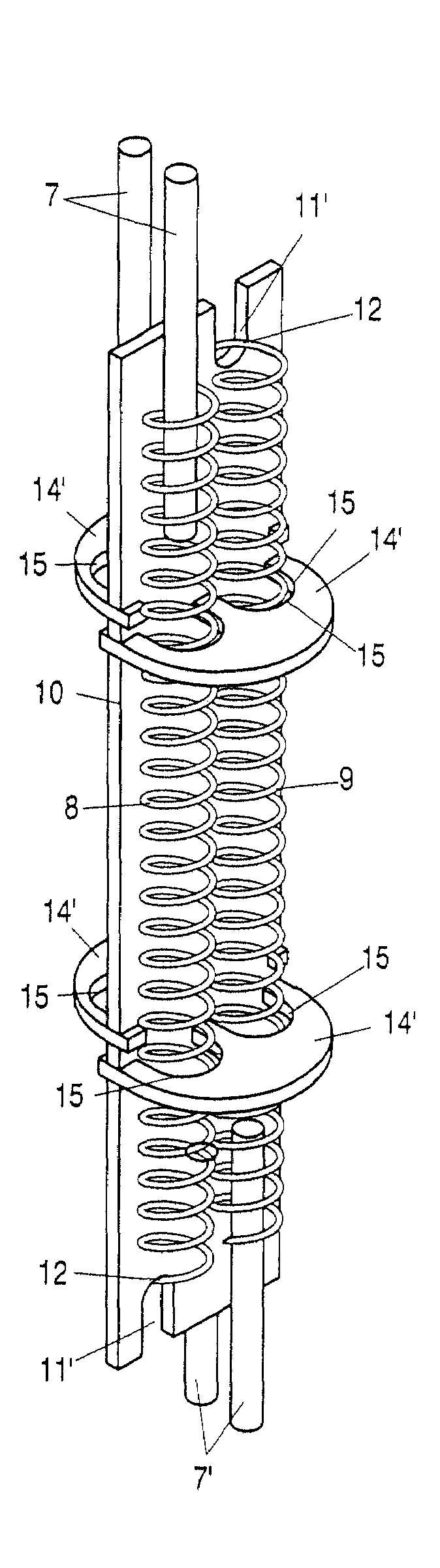
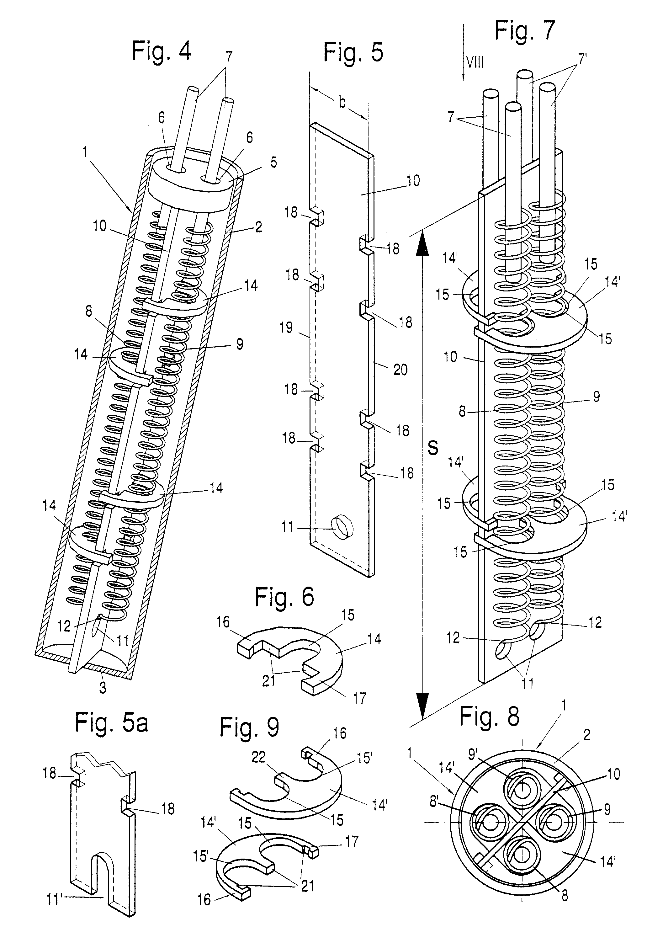
[0049]The closing disk 5 consists of an insulating material and is provided with passage openings 6 for terminal screws 7 of two heating coils 8 and 9. The two heating coils 8 and 9 extend on both sides of an insulating plate 10, which is arranged centrally in the tubular body 2 and acts as a carrier for the heating coils 8 and 9.

[0050]In the embodiment according to FIGS. 1 through 3 as well as FIGS. 4 and 5, the insulating plate 10 is provided, in the area of its lower end, with a recess 11 shaped as a hole, through which a coil section 12 connecting the two heating coils 8 and 9 to one another is led. As is shown in FIGS. 7 through 13, the recess may also be designed as an op...


PUM

PropertyMeasurementUnit
internal diameteraaaaaaaaaa
lengthaaaaaaaaaa
areaaaaaaaaaaa

Abstract

A cartridge heater, especially a compressed cartridge heater (1) has at least one heating coil (8, 9), which is arranged exposed in a metallic tubular body (2) and is embedded in a granulated insulating material. The ends of heating coil portions (8, 9) are provided with terminals (7) projecting from the tubular body (2). To make it possible to manufacture such a cartridge heater with minimal effort in terms of labor and material, a flat insulating plate (10) coordinated in its width with the internal diameter of the tubular body (2) is provided as the carrier. The heating coils (8, 9) extend along the two flat sides of the insulating plate (10) and the two heating coils (8, 9) are connected to one another by a coil section (12, 12′), which is led around a deflecting edge (27) of the insulating plate (10).

Description

CROSS REFERENCE TO RELATED APPLICATIONS[0001]This application claims the benefit of priority under 35 U.S.C. § 119 of German Patent Application DE 20 2005 011 686.6 filed Jul. 26, 2005, the entire contents of which are incorporated herein by reference.FIELD OF THE INVENTION[0002]The present invention pertains to a compressed cartridge heater with at least one heating coil, which is arranged exposed in a metallic tubular body and is embedded in a granulated insulating material and whose ends are provided with terminals projecting from the tubular body.BACKGROUND OF THE INVENTION[0003]A compressed cartridge heater of this type is known, for example, from DE 70 31 974 U. A plurality of heating conductor coils with different wire thicknesses and different coil diameters are accommodated in this cartridge heater concentrically with one another, exposed in a cylindrical cartridge housing, which has a fixed front-side bottom at one end and whose other end is closed by a metal disk with war...

Claims


Application Information

Patent Timeline
Patent Type & Authority Patents(United States)
IPC IPC(8): H05B3/06H05B3/78H05B3/04H05B3/42H05B3/44H05B3/48
CPCH05B3/04H05B3/48H05B3/44
Inventor SCHLIPF, ANDREAS
Owner TUERK HILLINGER
Why Eureka
Try Eureka