Apparatus for wiper die monitoring

a technology for wiper dies and accessories, applied in the field of accessories for wiper die monitoring, can solve the problems of insufficient waiting time for workpieces to show evidence of wear, unsuitability of /b> to the point of needing replacement or adjustment, and inability to adjust, etc., and achieve the effect of quick and easy detection

Inactive Publication Date: 2009-09-29
GM GLOBAL TECH OPERATIONS LLC
View PDF6 Cites 3 Cited by
  • Summary
  • Abstract
  • Description
  • Claims
  • Application Information

AI Technical Summary

Benefits of technology

[0008]The present invention provides sensors for monitoring a plurality of normal and axial pressures of the wiper die insert with respect to the wiper die holder, whereby the operator is enabled to quickly and easily detect when the wiper die insert is no longer able to provide bent tubular articles of sufficient quality.
[0013]Accordingly, it is an object of the present invention to provide a means to detect when the wiper die insert is approaching a condition in which it will no longer produce bent tubular workpieces of sufficient quality by monitoring drift of normal and axial pressure distributions of the wiper die insert with respect to the wiper die holder from nominal values.

Problems solved by technology

In low volume production, a skilled operator can visibly detect when the wiper die insert 26 has become unsuitable to the point of needing replacement or adjustment.
In a high volume setting, however, the traditional method of waiting for the workpieces to show evidence of this wear is inadequate.

Method used


Image

  • Apparatus for wiper die monitoring
  • Apparatus for wiper die monitoring
  • Apparatus for wiper die monitoring

Examples


Embodiment Construction

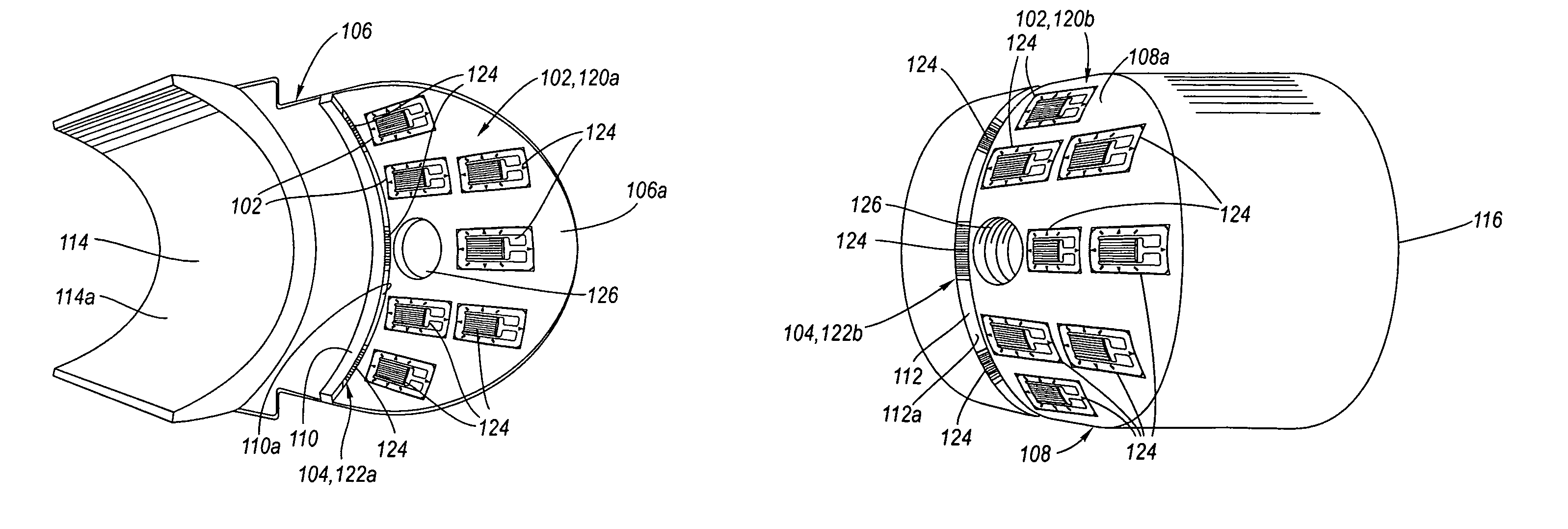
[0039]Referring now to the Drawing, FIGS. 6A through 15 depict various aspects of a pressure sensing wiper die insert, and methodology of use therefor, according to the present invention which includes a first set of pressure sensors for indicating normal pressure distribution and a second set of pressure sensors for indicating axial pressure distribution.

[0040]The pressure sensing the wiper die 100a, 100b, 100a′, 100b′ according to the present invention (see FIGS. 8 and 12) is composed of a wiper die holder 106 and a wiper die insert 108, which have mutually mating surfaces, a concave holder mating surface 106a (see FIGS. 6A and 10A) and a convex insert mating surface 108a (see FIG. 6B and FIG. 10B), which mating surfaces are complementing with respect to each other, and wherein one or the other mating surface has disposed thereat a first set of pressure sensors 102, as will be discussed in detail hereinbelow. Further, at an axial abutment 118, 118′ as between the wiper die holder ...


PUM

PropertyMeasurementUnit
pressureaaaaaaaaaa
axial pressureaaaaaaaaaa
axial pressuresaaaaaaaaaa

Abstract

In a rotary tube bender, a first set of pressure sensors is located between the normally disposed mating surfaces of a wiper die insert and its wiper die holder; and a second set of pressure sensors is located between the axially disposed surfaces of the wiper die insert and the wiper die holder. Signal outputs of the first and second sets of pressure sensors over the course of bending cycles are compared to previously determined nominal signal outputs for drift indicative of whether a realignment or replacement of the wiper die should be performed.

Description

TECHNICAL FIELD[0001]The present invention relates, in general, to dies used in the bending of tubular workpieces. More particularly, the present invention relates to an apparatus, and methodology of use therefor, for monitoring of the location and applied pressure characteristics of a wiper die insert of a rotary tube bender.BACKGROUND OF THE INVENTION[0002]The process of hydroforming is a metal forming process whereby specialized dies are used in conjunction with high pressure hydraulic fluid to force room temperature metal into the dies to form parts. An important application of hydroforming as used in the automotive industry is the creation of bent tubular parts. Many automotive bent tubular parts are produced utilizing a rotary tube bender, most commonly in the form of a “horizontal rotary draw bender”.[0003]FIGS. 1 through 3 schematically depict a rotary tube bender in the form of a horizontal rotary draw bender 10, as known in the art, which includes a set of four dies: a ben...

Claims


Application Information

Patent Timeline
Patent Type & Authority Patents(United States)
IPC IPC(8): B21D7/04
CPCB21D7/14B21D7/024
Inventor GHIRAN, MIKE M.MELLAS, SPYROS P.CRANTAS, WILLIAM M.MARKS, KEVIN R.WOHLENHAUS, DOUGLAS T.
Owner GM GLOBAL TECH OPERATIONS LLC
Why Eureka
Try Eureka