Composite tool insert

a tool insert and composite technology, applied in the field of tool inserts, can solve the problems of inconvenient use of diamond cutters in certain down the hole drilling operations, inability to meet the requirements of all substrates encountered, and inability to meet the requirements of diamond cutters

Active Publication Date: 2009-09-29
ELEMENT SIX PRODION +2
View PDF7 Cites 18 Cited by
  • Summary
  • Abstract
  • Description
  • Claims
  • Application Information

AI Technical Summary

Problems solved by technology

The diamond cutters, however, are not always suitable for all substrates encountered.
For instance, it is well established that diamond cutters cannot be used satisfactorily for milling or drilling through ferrous substrates such as steel.
As a result, the use of diamond cutters in certain down the hole drilling operations is not suitable as milling through a steel casing, which is used to line the vertical borehole or shaft, is required.
As PCD is not suitable for drilling through the steel casing due to reactions with the ferrous materials, an alternative drill bit insert is required.
As the drill strings that have to be removed are very long, this is a time consuming exercise that results in costly downtime.

Method used


Image

  • Composite tool insert
  • Composite tool insert

Examples


Embodiment Construction

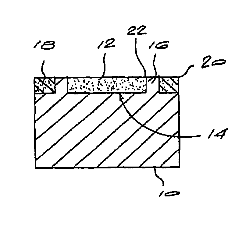
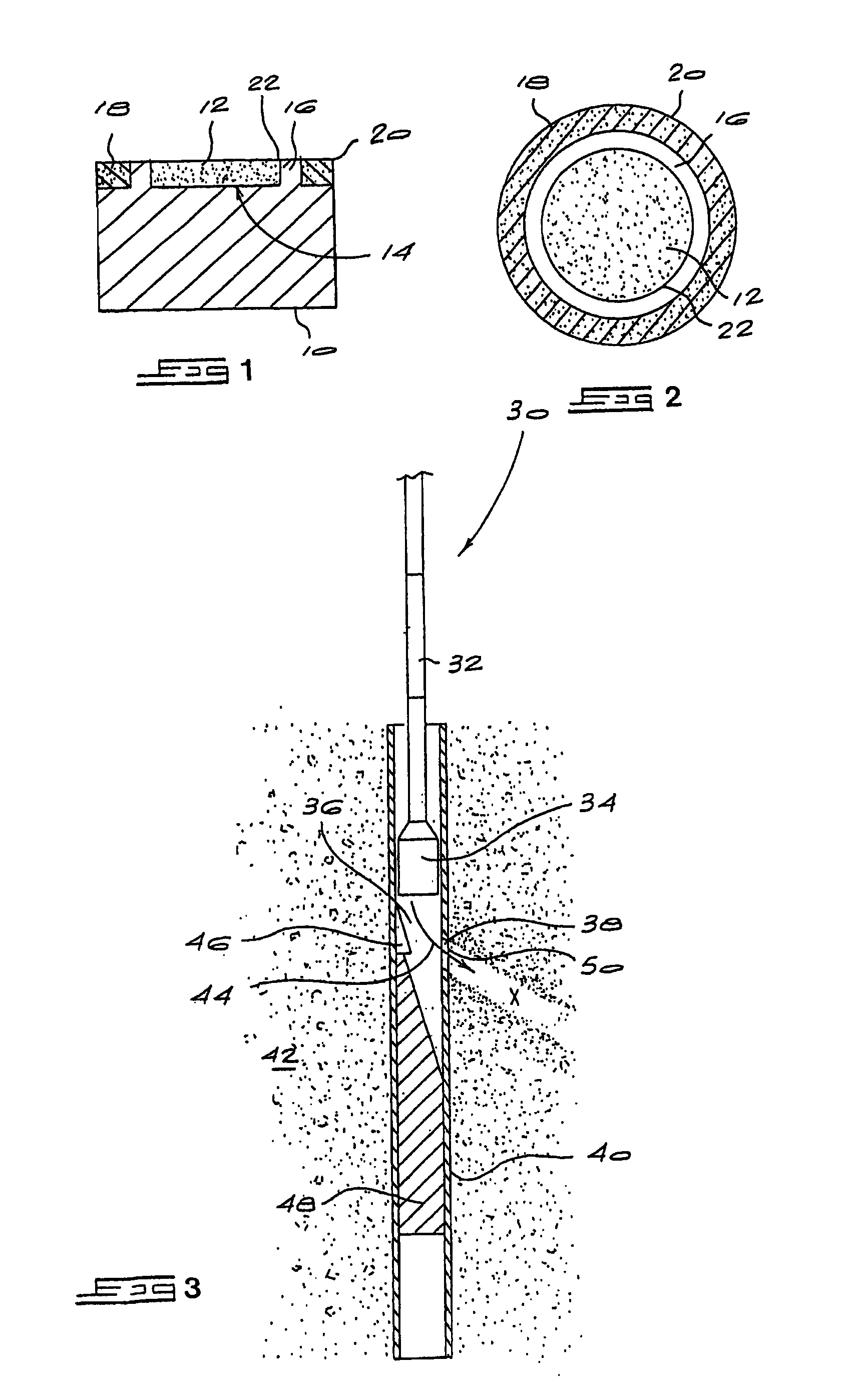
[0013]Referring to FIGS. 1 and 2, of the accompanying drawings, an embodiment of a tool insert of the invention is shown. The tool insert comprises a tungsten carbide substrate 10, a PCD layer 12 located within a recess 14 and surrounded by an annular section or ring16 of tungsten carbide extending laterally from a support surface 17, and a protective layer or ring 18 surrounding the ring 16.

[0014]The protective ring 18 may be formed of a different grade of tungsten carbide to that of the substrate 10 or, alternatively, be formed of tool steel or other appropriate material. The choice of material is dependent on the substance or substrate to be milled, drilled or cut before exposing the PCD layer 12. The protective ring 18 can be formed in situ or, alternatively, can be formed as a separate ring component which is attached to the tool insert. The protective ring 18 may be attached to the tool insert, which has been machined to accept the ring, for example by brazing, press fitting, ...


PUM


Abstract

A tool insert comprises a substrate (10) having a support surface and a support ring extending laterally from the support surface. The support ring is sized to define a recess (14) within the confines thereof and a shelf about the periphery thereof. A layer (12) of ultra-hard abrasive material is located within the recess and bonded to the substrate and the support ring (16), and presents a primary cutting edge (22) for the tool insert. A protective layer (18) is bonded to the shelf about the support ring so as to protect the primary cutting edge. The protective layer provides a secondary cutting edge (20) for the tool insert, the depth of the protective layer being selected so as to be sufficient to protect the primary cutting edge whilst cutting, milling or drilling through a first substance but to expose the primary cutting edge upon encountering a second substance.

Description

[0001]This application is a 371 of PCT / IB2003 / 003921 filed on Sep. 12, 2003,published on May 13, 2004 under publication number WO 2004 / 040096 A1 and claims priority benefits of South African Patent Application No. ZA 2002 / 8778 filed Oct. 30, 2002.BACKGROUND OF THE INVENTION[0002]THIS invention relates to a tool insert.[0003]The use of diamond compacts, also known as PCD, as cutting elements are well known in the art and used extensively in various cutting, drilling, milling and other abrasive operations due to the high abrasion resistant properties of diamond cutters. The diamond cutters, however, are not always suitable for all substrates encountered. For instance, it is well established that diamond cutters cannot be used satisfactorily for milling or drilling through ferrous substrates such as steel. As a result, the use of diamond cutters in certain down the hole drilling operations is not suitable as milling through a steel casing, which is used to line the vertical borehole or...

Claims


Application Information

Patent Timeline
Patent Type & Authority Patents(United States)
IPC IPC(8): E21B10/56E21B10/567E21B29/06
CPCE21B10/5676E21B29/06Y10T407/19
Inventor TANK, KLAUSCHAPMAN, RAYMOND ALBERTACHILLES, ROY DERRICK
Owner ELEMENT SIX PRODION
Why Eureka
Try Eureka