Lift boat leg

a technology for lifting boats and legs, applied in the direction of boat parts, artificial islands, construction, etc., can solve the problem of increasing the pressure of the bottom bearing of the truss/lattice legs

Inactive Publication Date: 2009-09-29
SANDERS RONALD
View PDF35 Cites 16 Cited by
  • Summary
  • Abstract
  • Description
  • Claims
  • Application Information

AI Technical Summary

Benefits of technology

[0009]In one embodiment, the present invention provides an improved jack up vessel that includes a hull, a plurality of legs (preferably three), a plurality of pads, one pad attached to each leg, and a jacking mechanism for movi

Problems solved by technology

Such truss/lattice legs increase botto

Method used


Image

  • Lift boat leg
  • Lift boat leg
  • Lift boat leg

Examples


Embodiment Construction

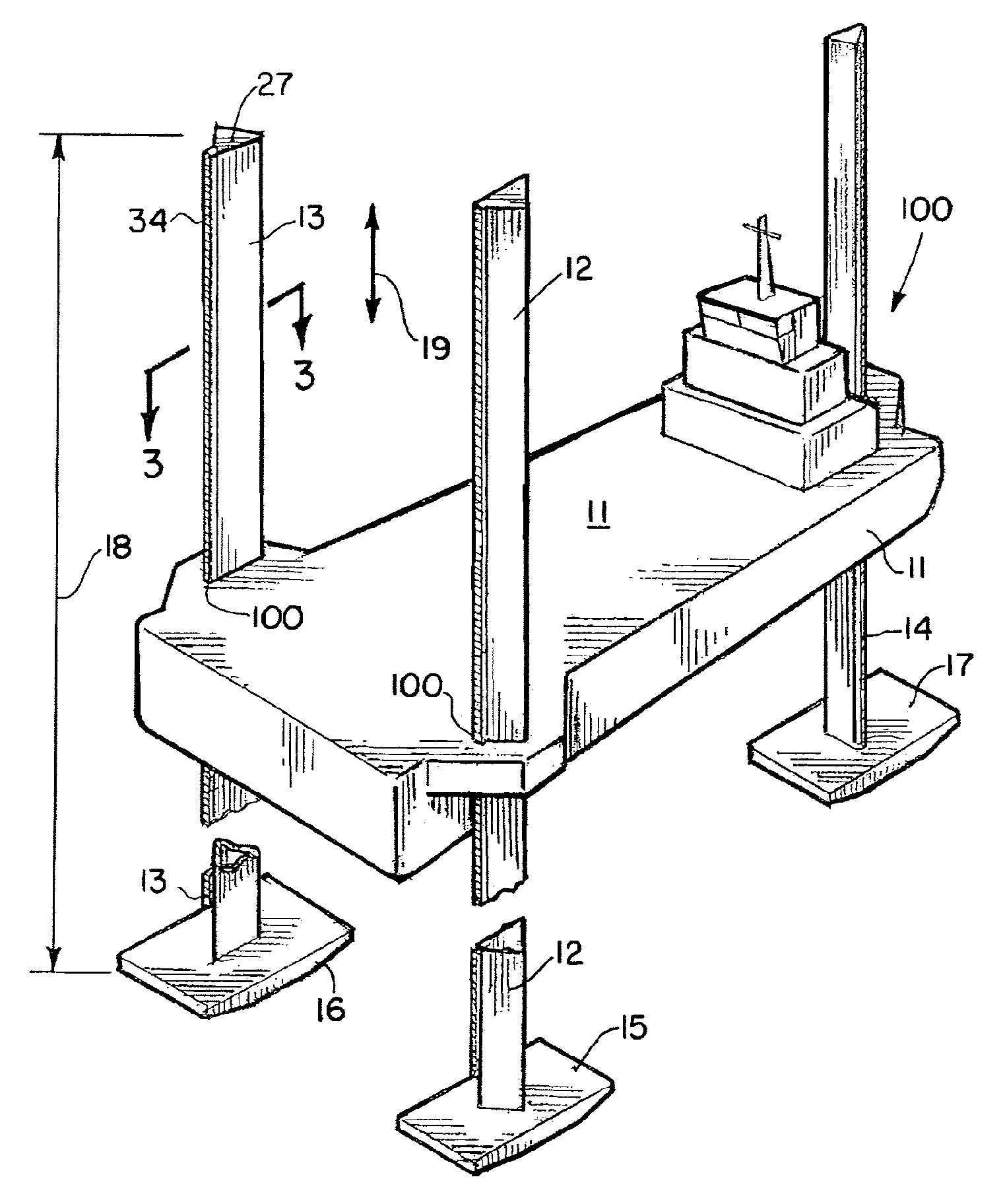
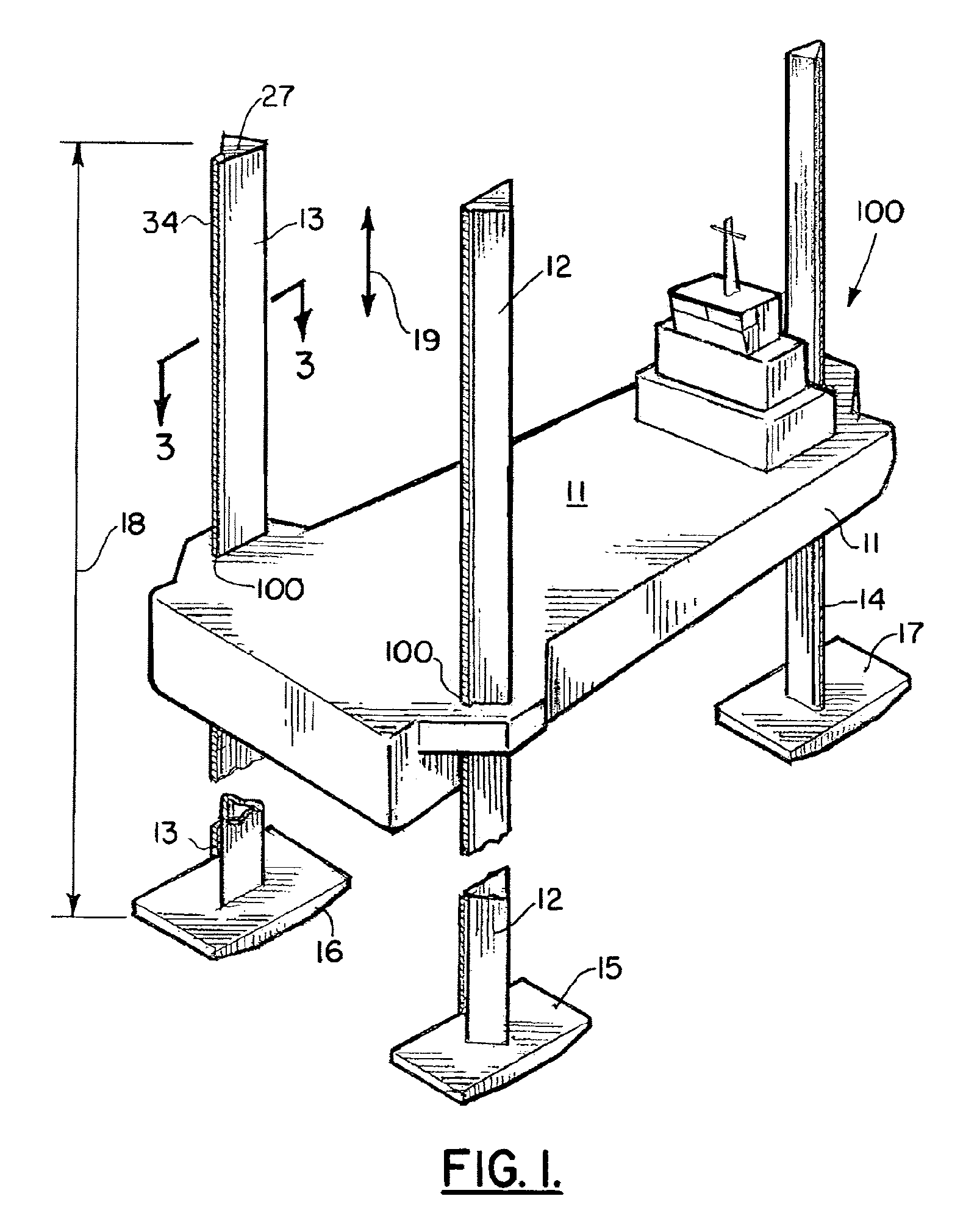
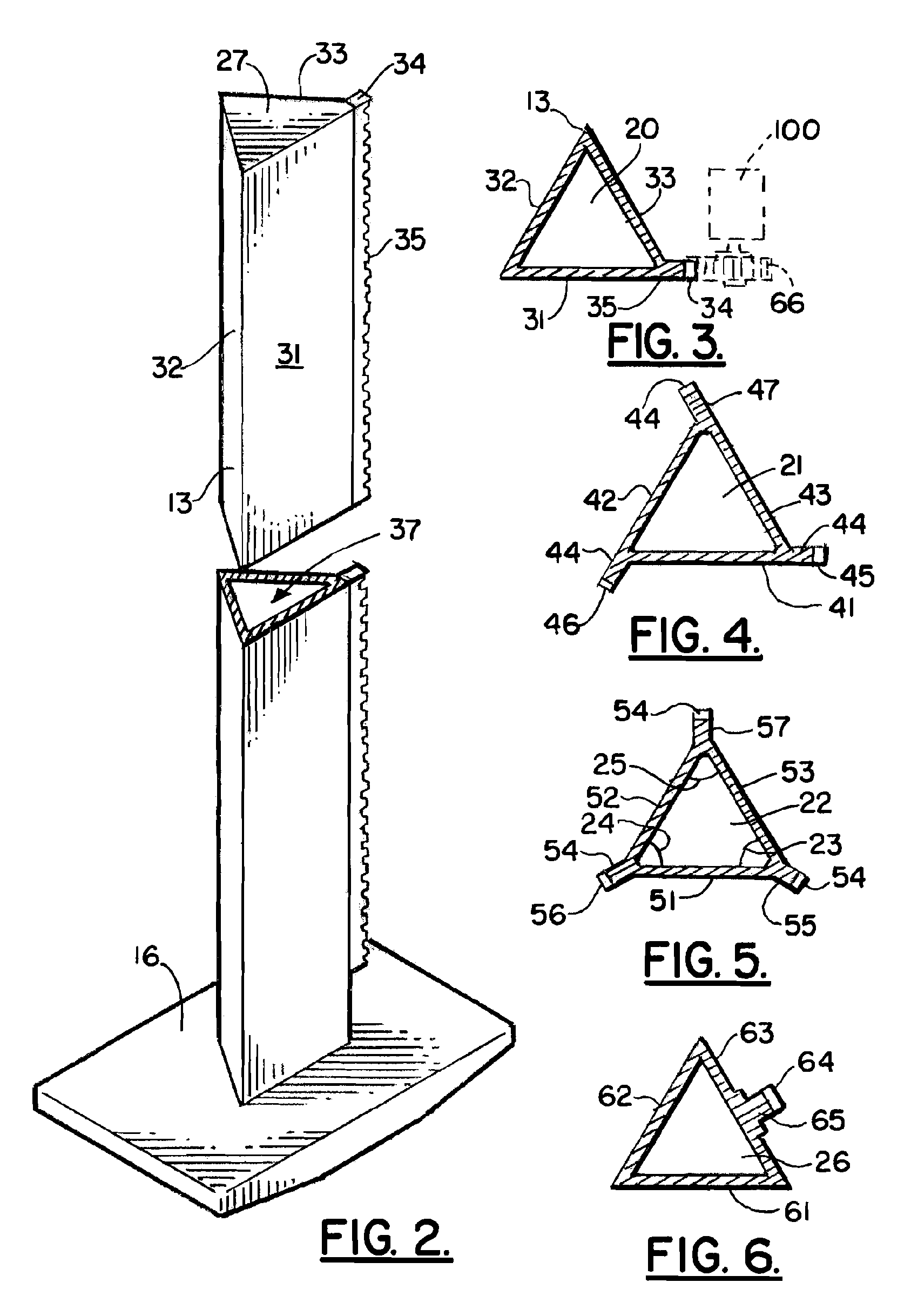
[0022]FIG. 1 shows the preferred embodiment of the apparatus of the present invention, designated generally by the numeral 10. Lift boat or jack up vessel 10 has a hull 11 and a plurality of legs (e.g., three legs 12, 13, and 14). Leg 12 can include pad or foot 15. Leg 13 can include pad or foot 16. Leg 14 can include pad or foot 15. Each leg 12, 13, 14 is preferably a closed wall, watertight member. Each leg 12, 12, 14 preferably has a generally triangular transverse cross section, such as those shown in FIGS. 3-10. Further, each leg 12, 13, 14 is preferably of a closed wall, non-lattice or non-truss construction. Each leg 12, 13, 14 can be of welded steel construction, for example.

[0023]In one embodiment a cross section comprises three sides which can be triangular in shape. In one embodiment at least one lifting portion is included which includes a lifting rack. In one embodiment a plurality of lifting portions are included, each including a lifting rack. In one embodiment each l...


PUM


Abstract

An improved jack up vessel includes a hull, a plurality of legs, each leg having a pad, and a jacking mechanism for moving the hull upward and downward. Each leg is a generally triangular leg that is a closed wall, buoyant structure.

Description

CROSS-REFERENCE TO RELATED APPLICATIONS[0001]Priority of U.S. Provisional Patent Application Ser. No. 60 / 941,429, filed Jun. 1, 2007, incorporated herein by reference, is hereby claimed.STATEMENT REGARDING FEDERALLY SPONSORED RESEARCH OR DEVELOPMENT[0002]Not applicableREFERENCE TO A “MICROFICHE APPENDIX”[0003]Not applicableBACKGROUND[0004]The present invention relates to lift boats or jack-up boats that feature a hull having a plurality of legs, each leg having an associated jacking mechanism that enables the hull to be elevated or lowered relative to the legs and wherein each leg has a load bearing pad that engages the seabed during use. More particularly, the present invention relates to an improved lift boat having an improved leg configuration that contributes buoyance by providing a specially shaped and watertight leg that has one or more racks that engage pinion gear(s) of a drive or jacking unit.[0005]Lift boats are well known in the art. These devices are also referred to as...

Claims


Application Information

Patent Timeline
IPC IPC(8): E02B17/08
CPCB63B21/50E02B17/021E02B17/0818E02B2017/0082E02B2017/0056
Inventor SANDERS, RONALD
Owner SANDERS RONALD
Why Eureka
Try Eureka