Application tool for coaxial cable compression connectors

a technology for compression connectors and coaxial cables, applied in the direction of metal working equipment, connection formation by deformation, manufacturing tools, etc., can solve the problems of affecting the performance of compression connectors, and affecting the quality of compression connectors

Active Publication Date: 2009-10-06
IDEAL IND INC
View PDF10 Cites 26 Cited by
  • Summary
  • Abstract
  • Description
  • Claims
  • Application Information

AI Technical Summary

Benefits of technology

[0004]The present invention provides a tool for installing compression connectors of various sizes and types on the end of a coaxial cable without the need for multiple tools or components. The tool of the present invention has a pair of movable anvils for engaging two different lengths of connectors and a fixed anvil for engaging a third length of connector. The movable anvils have an aperture which defines a throat that is large enough to permit easy entry and exit of a cable and small enough to apply a suitable retention force so that a cable will not inadvertently come out of or move around in the aperture prior to compression. The anvils each have a pair of movable spring clips with a depression or cutout in an edge thereof such that opposed spring clips define the cable-receiving receptacle. A connector seated at the proper location on the end of the cable is placed between the plunger and face of the anvil with the cable extending through the aperture in the anvil. Then the plunger is actuated to compress the connector and fix it in place on the cable. After retraction of the plunger a radial movement of the finished cable / connector combination is all that is needed to remove the finished cable from the compression zone. The arrangement of the anvil apertures is such that separate releasing activation of the spring clips is not necessary. In an alternate embodiment, the anvil may have a tear-drop shaped aperture, either with or without a throat.

Problems solved by technology

One disadvantage of early compression tools is the compression chamber is sized to accept only a single size or type of connector.
However, this requires the technician to change out the tool parts every time a different size connector is encountered.
Time is lost performing the change.
Furthermore, this type of multiple component tool still does not remove the need to have separate tools or components for separate sizes of connectors.
While this allows the tool to be used on two different connector sizes, it introduces problems of its own.
Chief among these is the inability to release a finished cable / connector combination without separate manipulation of the split bases.
Now the finished cable is ready for release from the tool but the split bases will not readily release it.
Neither of these methods of releasing a finished cable from the tool is convenient.
It has also been found that this tool does not work well with RG-11 F-type compression connector.

Method used


Image

  • Application tool for coaxial cable compression connectors
  • Application tool for coaxial cable compression connectors
  • Application tool for coaxial cable compression connectors

Examples


Embodiment Construction

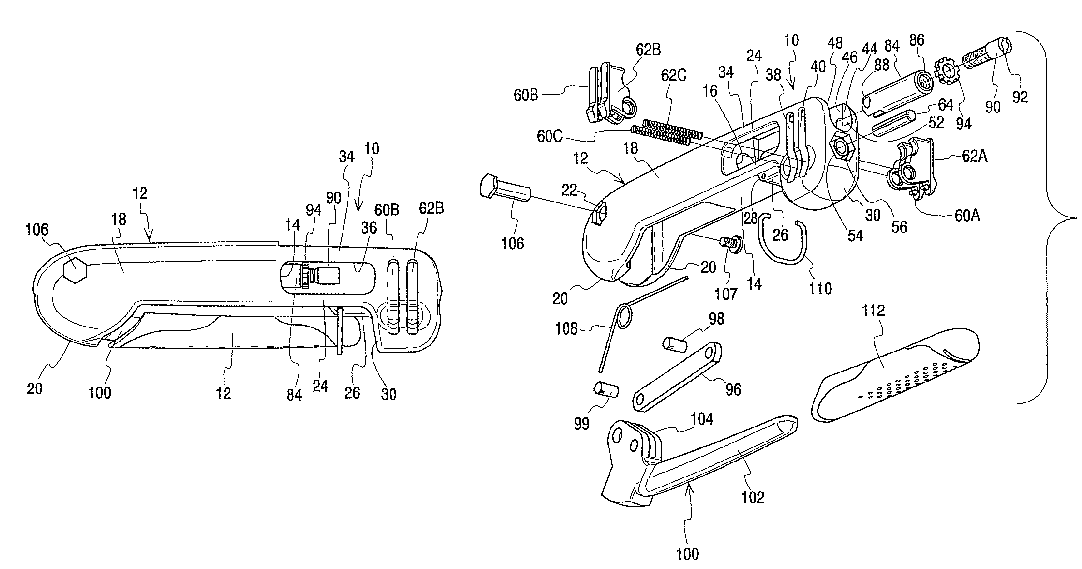
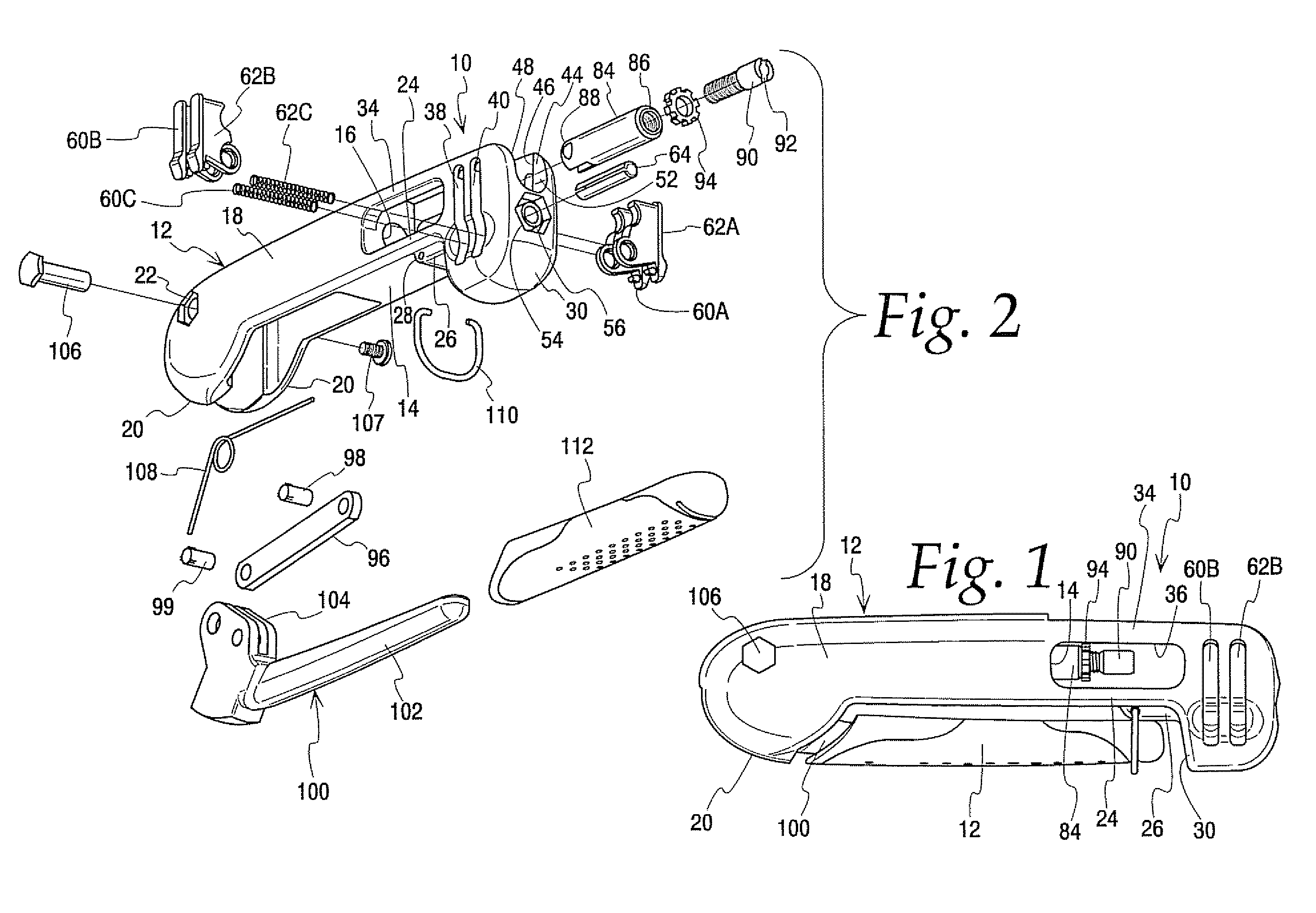
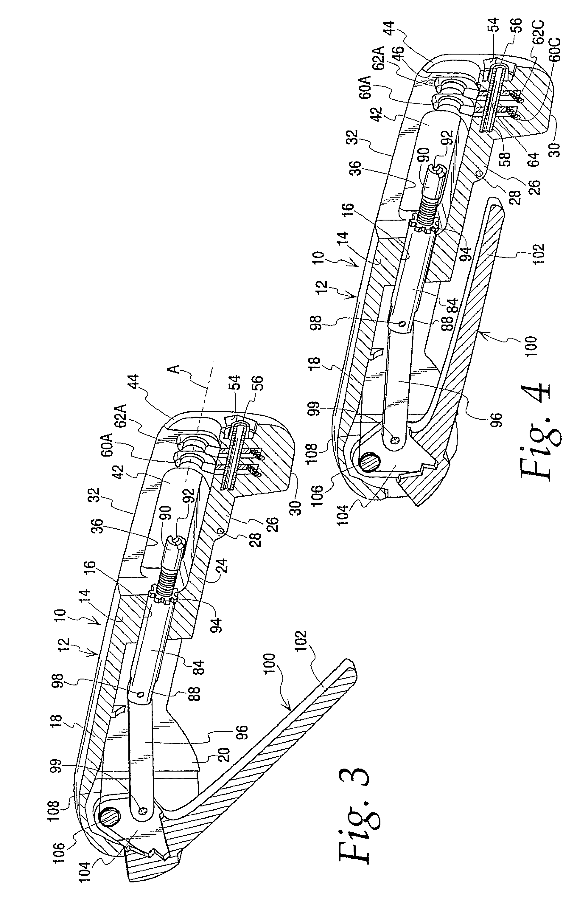
[0022]FIG. 1 illustrates the application tool of the present invention generally at 10. The tool includes a base 12. The details of the base are best seen in FIGS. 2 and 3. The base includes a central block member 14 having a bore 16 formed therein. A generally three-sided heel section 18 extends rearwardly from the block member. The heel section is hollow and open at its lower side. Rounded ears 20 are formed at the rear of the heel 18. There are transverse, aligned holes 22 in the heel above the ears 20. Extending forwardly of the block member 14 is a beam 24. About midway along the beam there is an enlargement 26 which includes a transverse hole 28. Forwardly of the enlargement 26 the front portion of the beam 24 carries a depending anvil mount 30. Above the anvil mount there are two side walls 32, 34 joined to the beam 24. The side walls extend back to the block member 14. There are windows 36 in the side walls. Two transverse slots 38, 40 are formed in the anvil mount 30. These...


PUM

PropertyMeasurementUnit
closure angleaaaaaaaaaa

Abstract

A tool for installing compression connectors of various sizes and types on the end of a coaxial cable has a base mounting at least one movable anvil for engaging at least one length of connector. The base further incorporates a fixed anvil for engaging at least a second length of connector. The movable anvil defines an aperture or exit surfaces shaped to permit easy entry and exit of a cable while still applying a suitable retention force to an inserted cable. A slidably mounted plunger cooperates with the anvils to compress a connector.

Description

BACKGROUND OF THE INVENTION[0001]This invention relates to a tool for installing compression connectors on the end of coaxial cable. Such connectors come in a variety of styles and sizes. Among the styles are F-type, BNC and RCA connectors. Among the sizes are RG-6, RG-11 and RG-59. Details of the three connector styles are shown in U.S. Pat. No. 7,153,159. Installation of each style of compression connector entails inserting the prepared end of a coaxial cable a predetermined distance into the connector and then compressing the connector to deform a portion of it and lock it onto the cable. Compression tools for performing this function are known. Such tools have a zone which receives a connector pressed onto the end of a coaxial cable. A compressive force then is applied to the ends of the connector to deform the connector and complete the installation.[0002]One disadvantage of early compression tools is the compression chamber is sized to accept only a single size or type of conn...

Claims


Application Information

Patent Timeline
Patent Type & Authority Patents(United States)
IPC IPC(8): H01R43/02
CPCH01R43/042H01R43/058H01R9/05Y10T29/53213Y10T29/53278Y10T29/53226Y10T29/53235Y10T29/53265Y10T29/49185Y10T29/53209Y10T29/53257
Inventor SUTTER, ROBERT W.SKEELS, STEPHEN J.
Owner IDEAL IND INC
Why Eureka
Try Eureka