Pneumatic pressure relief test plug

a technology of pneumatic testing and test plugs, which is applied in the direction of mechanical equipment, transportation and packaging, and functional valve types, etc., can solve the problems of damage to test plugs, problems such as leakage, and inability to provide protection for overinflation, so as to facilitate the removal of pneumatic test plugs and facilitate sealing

Active Publication Date: 2009-10-06
IPS
View PDF34 Cites 30 Cited by
  • Summary
  • Abstract
  • Description
  • Claims
  • Application Information

AI Technical Summary

Benefits of technology

[0008]Some embodiments further comprise a collar and the collar is configured to couple the first portion of the inflation valve to an open end of the bladder. In some embodiments, the inflation valve is insert-molded inside an open end of the bladder. In some embodiments, the interior end the inflation valve includes a flange and a release channel inlet, the flange defining an edge surface and the release channel inlet being located above the flange and leading to the release channel, wherein the sealing portion of the bladder wall substantially surrounds the edge surface of the flange and blocks the release channel inlet, and wherein overinflation of the bladder causes a portion of the interior surface of the bladder wall to separate from the edge surface of the flange, thus releasing air from the interior area of the bladder around the edge surface of the flange and into the release channel inlet. In some embodiments, the inflation valve further includes a Schrader valve located approximately in the center of the inflation valve, and the Schrader valve is configured to allow pressurized air to enter the interior area of the bladder and to allow manual depressurization of the bladder. In some embodiments, the Schrader valve is insert-molded inside the inflation valve. In some embodiments, the bladder wall includes one or more ribs disposed around the exterior surface of the bladder wall, and wherein the one or more ribs are configured to facilitate sealing against the internal pipe wall. Some embodiments further comprise a handle device, wherein the handle device is configured to facilitate removal of the pneumatic test plug from the pipe in an uninflated position.

Problems solved by technology

Although some existing pneumatic test plugs may display a maximum inflation pressure on the outside of the bladder, this does not provide protection for overinflation, but instead relies on the diligence of the operator and the existence and accuracy of an air inlet pressure gauge.
If the elastomeric bladders of such pneumatic test plugs were to be overinflated, problems could occur.
These problems may include damage to the test plug, damage to the pipe system, and / or other inconveniences for the operator.
A proposed solution to this problem involves using an external pressure regulator or external pressure relief device on the air inlet, but these solutions are cumbersome and are often ignored by operators.
They also increase the time required to inflate the bladder.
Other existing pneumatic test plugs include integrated pressure relief devices; however, the present inventors have found that these particular pressure relief devices tend to leak, do not provide repeatable results, and may disrupt testing of the pipe system.
The present inventors have found that pneumatic test plugs employing the former pressure relief devices may be prone to fouling and tend to collect contamination, thus negatively affecting their performance.
Similarly, the present inventors have found that pneumatic test plugs employing the latter pressure relief devices may release excess air into the enclosed area of the pipe system behind the test plug, thus tending to force the test plug out of the clean-out access area and disrupting the test.

Method used


Image

  • Pneumatic pressure relief test plug
  • Pneumatic pressure relief test plug
  • Pneumatic pressure relief test plug

Examples


Embodiment Construction

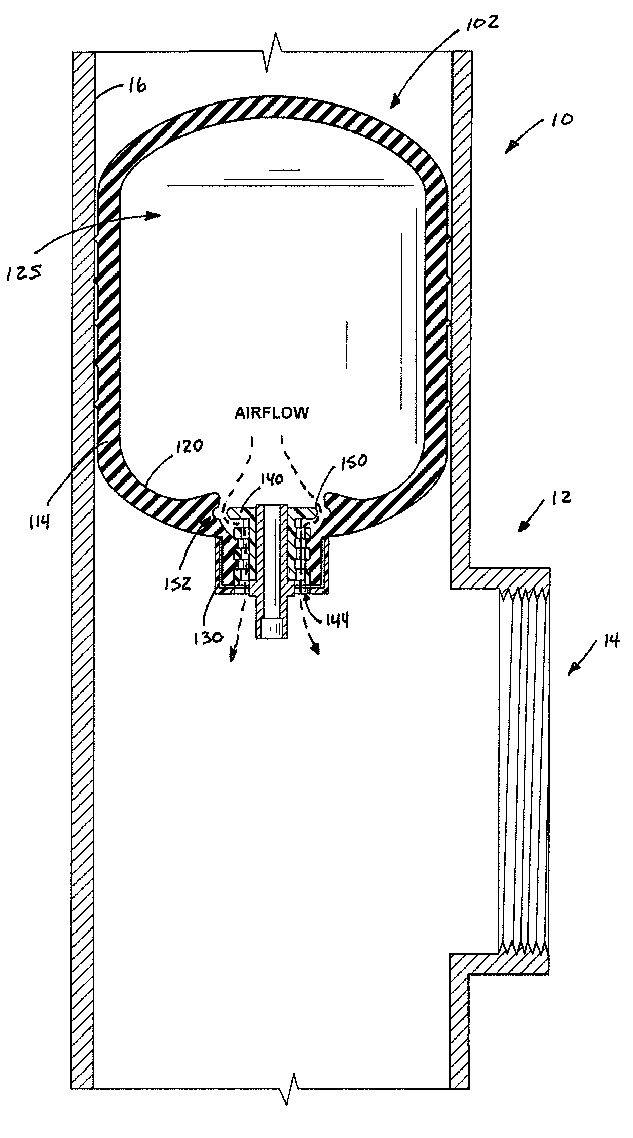
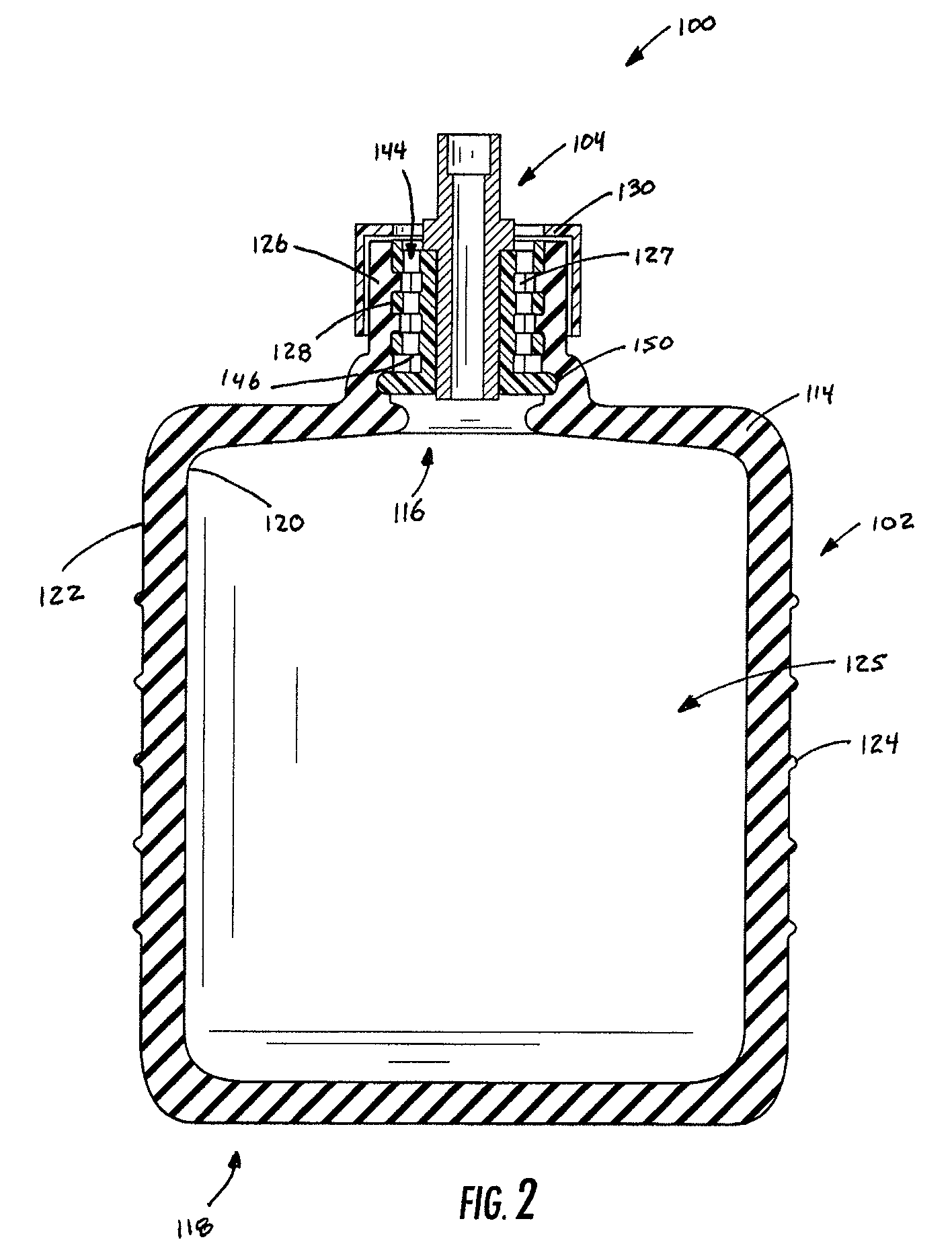
[0007]The present invention addresses the above needs and achieves other advantages by providing a pneumatic test plug for use with a pipe having a generally cylindrical internal pipe wall. In general, the pneumatic test plug includes an inflatable bladder formed by a bladder wall that is elastically deformable, and an inflation valve mounted in the bladder wall such that an interior end of the inflation valve is in fluid communication with an interior area defined within the bladder. The inflation valve defines a main air passageway through which air is introduced into the interior area, and a separate release channel having an inlet disposed toward the interior end of the inflation valve and an outlet in fluid communication with an exterior environment outside the bladder. The valve is mounted in the bladder wall such that a sealing portion of the bladder wall when in a sealed position engages the interior end of the inflation valve and sealingly closes the inlet of the release ch...


PUM


Abstract

The present invention provides a pneumatic test plug that seals a portion of a pipe section having a generally cylindrical internal pipe wall. In general, the pneumatic test plug includes an inflation valve mounted in the bladder wall of an inflatable bladder. The inflation valve includes a main air passageway through which air is introduced into the bladder and a separate release channel. The separate release channel includes an inlet disposed toward an interior end of the inflation valve and an outlet in fluid communication with an exterior environment outside the bladder. When in a sealed position, a sealing portion of the bladder engages the interior end of the inflation valve and sealingly closes the inlet of the release channel. When the sealing portion is elastically deflected by overinflation of the bladder, the sealing portion uncovers the inlet of the release channel to allow air to escape from the interior area of the bladder through the release channel to the exterior environment.

Description

FIELD OF THE INVENTION[0001]The present invention relates to plug devices for use in pipe systems, and more particularly to pneumatic test plug devices for sealing pipes or conduits at access ports and tee-connections.BACKGROUND OF THE INVENTION[0002]Pipe or plumbing systems often include access openings or ports that allow the interior of the pipes of the pipe system to be inspected and / or cleaned. Access opening configurations for such pipe systems can vary in size and shape, although many configurations are standardized. In one common configuration, an access opening (often referred to as a “clean-out”) is provided at the end of a relatively short section of cylindrical pipe that extends away from the axis of the main pipe section. Clean-outs may extend from a main pipe section at any angle. Those that extend approximately 90 degrees from the main pipe section are commonly called “clean-out tees” (referring to the T-shape created by the intersecting pipe sections). Other access o...

Claims


Application Information

Patent Timeline
Patent Type & Authority Patents(United States)
IPC IPC(8): F16L55/12
CPCF16L55/1286Y10T137/36Y10T137/3646
Inventor PETERSON, STEPHENLARSON, RICHARD
Owner IPS
Why Eureka
Try Eureka