Method and apparatus for embedded encoding of overlay data ordering in an in-situ interferometer

an interferometer and overlay technology, applied in the field of optical metrology, can solve the problems of data corruption, high cost, and high cost of a photolithographic system

Inactive Publication Date: 2009-10-06
LITEL INSTR
View PDF9 Cites 9 Cited by
  • Summary
  • Abstract
  • Description
  • Claims
  • Application Information

AI Technical Summary

Benefits of technology

[0019]Another embodiment of embedded encoding of overlay data ordering includes exposing a reticle pattern onto a substrate with a recording media, the reticle comprising a plurality of alignment attributes. The plurality of alignment attributes include an array of aberration determining structures and an array plurality of reference structures wherein one or more of the alignment attributes at predetermined sites on the reticle are modified. Then measuring the exposed reticle pattern and determining if measurements indicating modified alignment attributes within the exposed reticle pattern correlate to the predetermined sites of the reticle. The modification of the alignment attribute includes changing the width of the alignment attribute. The alignment attribute that is modified can be an aberration determining structure, or a reference structure or both.
[0020]Still another embodiment of embedded encoding of overlay data ordering inc...

Problems solved by technology

Today, these photolithographic systems are pushed to performance limits.
If one simply assumes that the overlay tool has identified the correct alignment attribute and proceeds to use the program for production measurements, the data can become corrupt.
In addition, many times the alignment attributes and wafer exposure patterns are symmetric with respect to the notch of the wafer, and simple rotations of the w...

Method used


Image

  • Method and apparatus for embedded encoding of overlay data ordering in an in-situ interferometer
  • Method and apparatus for embedded encoding of overlay data ordering in an in-situ interferometer
  • Method and apparatus for embedded encoding of overlay data ordering in an in-situ interferometer

Examples


first embodiment

Missing Teeth

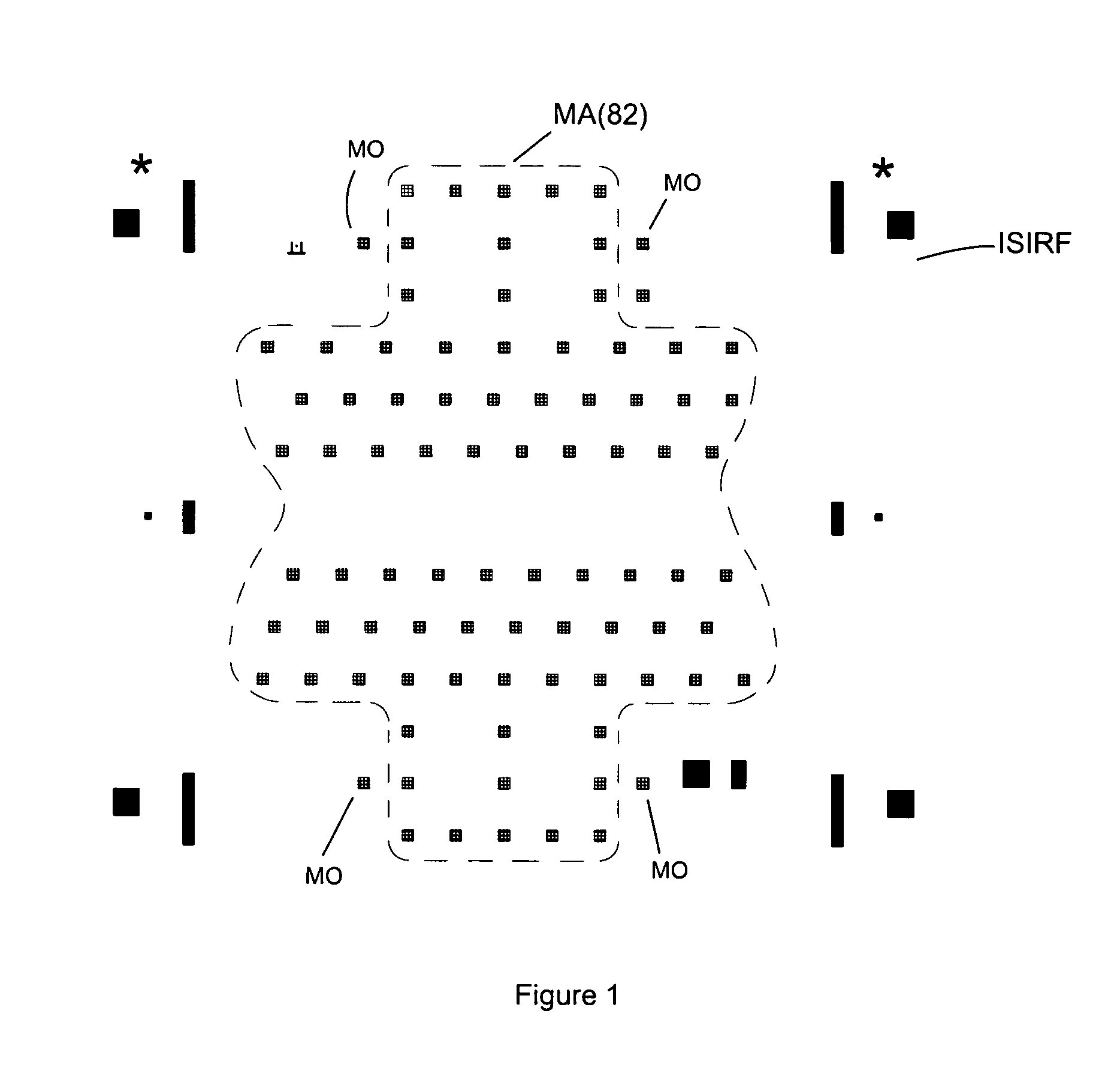
[0038]FIG. 6 shows a schematic of operation and illustration for in-situ interferometers. An example of an in-situ interferometer is detailed in U.S. Pat. No. 5,978,085 supra. The In-Situ Interferometer, (ISI) according to U.S. Pat. No. 5,978,085 supra is placed in a projection imaging tool (PIT). FIG. 6 is a block diagram illustrating portions of an In-Situ Interferometer exposure sequence. FIG. 6 illustrates an illuminator block (ILB) and a projection lens block (PLB). During exposure, an encoded face of an ISI (ISIRF) is illuminated by illuminator block, ILB, and an illuminator modification optic (L) that is part of the ISI. Angular subtense and chief ray direction are modified in a position dependent sense by pinhole (PH) and a projected field (PF) consisting of a multiplicity of projected aberration carrying structures (PMA)—images of which are printed on wafer W during the first exposure. Following the first exposure, reticle blades in ILB (not shown) are adjusted...

second embodiment

Second Variation of Second Embodiment

Non-Coupling Offsets with Global NCO Adjustments

[0097]While the second embodiment detailed NCO patterns on a local level for each field point using possibly a curl pattern (FIG. 10) for each field point the second variation of the second embodiment adds or superimposes a global pattern across the reticle field consisting of say ˜25 field points or 25 groups of MA and MO patterns (the number or MA patterns depends on the ISI reticle design per U.S. Pat. No. 5,978,085 supra). This just means that in addition to having identical curl type patterns for each MA field point (FIG. 10) one can also modify each curl pattern to give a global relationship as well as a local relationship (FIG. 14). FIG. 14 is a schematic illustrating curl patterns of varying magnitude and direction are shown at four separate field points (FP1 through FP4). For example, one might simply add a constant value (DXY) to each NCO field point vector (DXNCO, DYNCO) (IX, IY) or (DXNC...

third embodiment

Alignment Attribute CD Width Adjustments

[0102]If the overlay reader is equipped with an optical CD measurement tool it is also possible to encode an ISI reticle by modification of the physical size (width) of the alignment attribute instead of removing MA or MO structures as describe in the first embodiment. For example in the case of a bar-in-bar pattern one can simply change the bar-width, BW, (not length) of an alignment attribute substructure from say 1 um to 2 um (see BW FIG. 4) for select MA patterns. The benefit of this technique is that it is independent of overlay measurement (as long as the signal to noise ratio is not affected on the read out signal) and does not require interpolation to reconstruct the aberration wavefront (see above); however, it does take more time to process a wafer using CD measurements. The process is the same as described in FIG. 5 except here we use modified bar-in-bar substructures (increase in the physical thickness of a bar for example) and the...


PUM


Abstract

A method and apparatus for embedded encoding of overlay data ordering in an in-situ interferometer is described. An in-situ interferometer is encoded, or augmented, with special or missing alignment attributes at desired positions. Exposing a sequence of the encoded in-situ interferometer onto a silicon wafer coated with a suitable recording media. Then measuring the alignment attributes. The encoded overlay data is processed to verify the proper order and physical location of each overlay measurement. The data is collected without increasing the overall number of required overlay measurements required. Collection of overlay data allows for the proper reconstruction of the aberrated wavefront. Non-coupling alignment attribute offsets can also be used to perform similar operations using singular value decomposition and null space operations.

Description

REFERENCE TO RELATED APPLICATION[0001]This application claims priority benefit of U.S. provisional Application Ser. No. 60 / 634,791 filed Dec. 8, 2004 entitled “Method and Apparatus for Embedded Encoding of Overlay Data Ordering in an In-Situ Interferometer” by Smith et al. Priority of the filing date of the prior application is hereby claimed, and the disclosure of the prior application is hereby incorporated by reference in its entirety.BACKGROUND[0002]1. Field[0003]The present invention relates generally to optical metrology and, more particularly, to photolithography used in semiconductor manufacturing.[0004]2. Description of the Related Art[0005]Over the past thirty years the microelectronics industry has experienced dramatic rapid decreases in critical dimension by moving constantly improving photolithographic imaging systems. Today, these photolithographic systems are pushed to performance limits. As the semiconductor industry rapidly approaches limits of optical lithography, ...

Claims


Application Information

Patent Timeline
IPC IPC(8): G03F9/00
CPCG03F7/70633
Inventor SMITH, ADLAI H.HUNTER, JR., ROBERT O.BENDIK, JR., JOSEPH J.
Owner LITEL INSTR
Why Eureka
Try Eureka