Gas exhaust nozzle for a bypass turbomachine having an exhaust or throat section that can be varied by moving the secondary cowl

a bypass turbomachine and nozzle technology, which is applied in the direction of engine manufacturing, climate sustainability, sustainable transportation, etc., can solve the problems of difficult to adapt to the nozzles of civilian turbomachines and relatively expensive fabrication of variable section nozzles

Active Publication Date: 2009-10-13
SN DETUDE & DE CONSTR DE MOTEURS DAVIATION S N E C M A
View PDF31 Cites 11 Cited by
  • Summary
  • Abstract
  • Description
  • Claims
  • Application Information

AI Technical Summary

Benefits of technology

[0007]The main object of the present invention is thus to mitigate such drawbacks by proposing a gas exhaust nozzle for a bypass turbomachine that presents an exhaust or throat section that is geometrically variable as a function of the operating speed of the turbomachine.
[0009]By moving the movable portion of the primary cowl longitudinally upstream or downstream, it is possible to enlarge or reduce the exhaust section or the throat section of the nozzle in continuous and accurate manner depending on the operating speed of the turbomachine. This system thus presents numerous advantages, in particular those of being robust, accurate, compatible with existing nozzles, adding relatively little weight, and being easy to mount on bypass turbomachines used in civilian applications. In particular, it can easily be fitted to nozzles where thrust reversal is obtained by moving the secondary cowl in translation.
[0010]The presence of patterns disposed extending the trailing edge of the stationary portion of the secondary cowl serves firstly to reduce the parasitic drag produced by the “step” that inevitably appears between the stationary and moving portions of the secondary cowl during displacement of the movable portion, and secondly to contribute to reducing sound emission in any of the positions of the movable portion of the secondary cowl.

Problems solved by technology

Unfortunately, those techniques are difficult to adapt to the nozzles of civilian turbomachines.
This is due in particular to constraints associated with how the nacelle is installed relative to the wing of the airplane, to ground clearance, and to the thicknesses and the shapes of the trailing edges of the nacelle.
In addition, such variable section nozzles are relatively expensive to fabricate.

Method used


Image

  • Gas exhaust nozzle for a bypass turbomachine having an exhaust or throat section that can be varied by moving the secondary cowl
  • Gas exhaust nozzle for a bypass turbomachine having an exhaust or throat section that can be varied by moving the secondary cowl
  • Gas exhaust nozzle for a bypass turbomachine having an exhaust or throat section that can be varied by moving the secondary cowl

Examples


Embodiment Construction

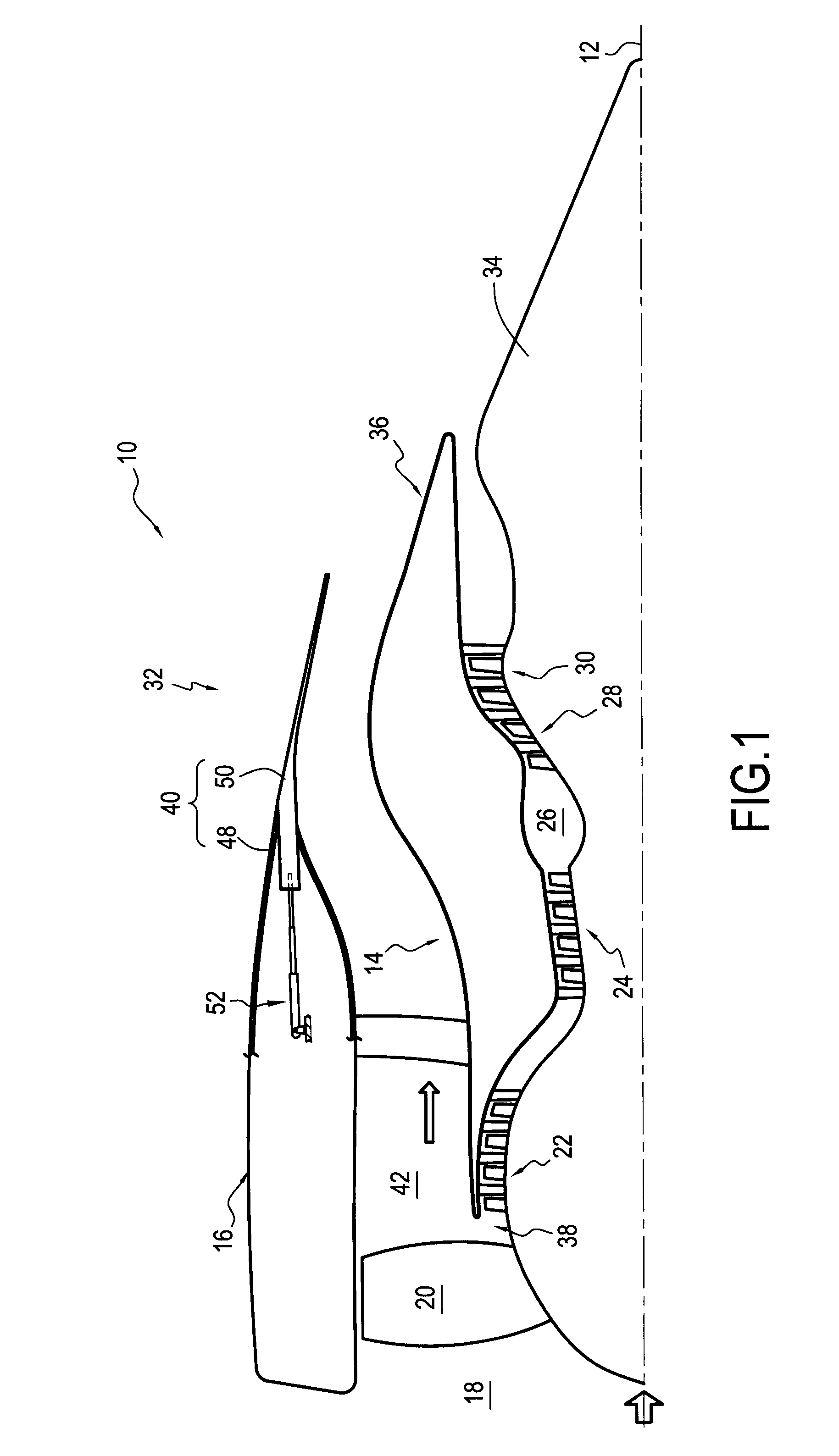
[0018]FIG. 1 is a highly diagrammatic longitudinal section view showing half of a bypass turbomachine 10 fitted with a nozzle of the invention. The turbomachine has a longitudinal axis 12 and comprises a gas turbine engine 14 and an annular nacelle 16 centered on the axis 12 and disposed concentrically around the engine.

[0019]From upstream to downstream in the flow direction of a stream of air passing through the turbomachine, the engine 14 comprises: an air inlet 18; a fan 20; a low-pressure compressor 22; a high-pressure compressor 24; a combustion chamber 26; a high-pressure turbine 28; and a low-pressure turbine 30, each of these elements being disposed along the longitudinal axis 12.

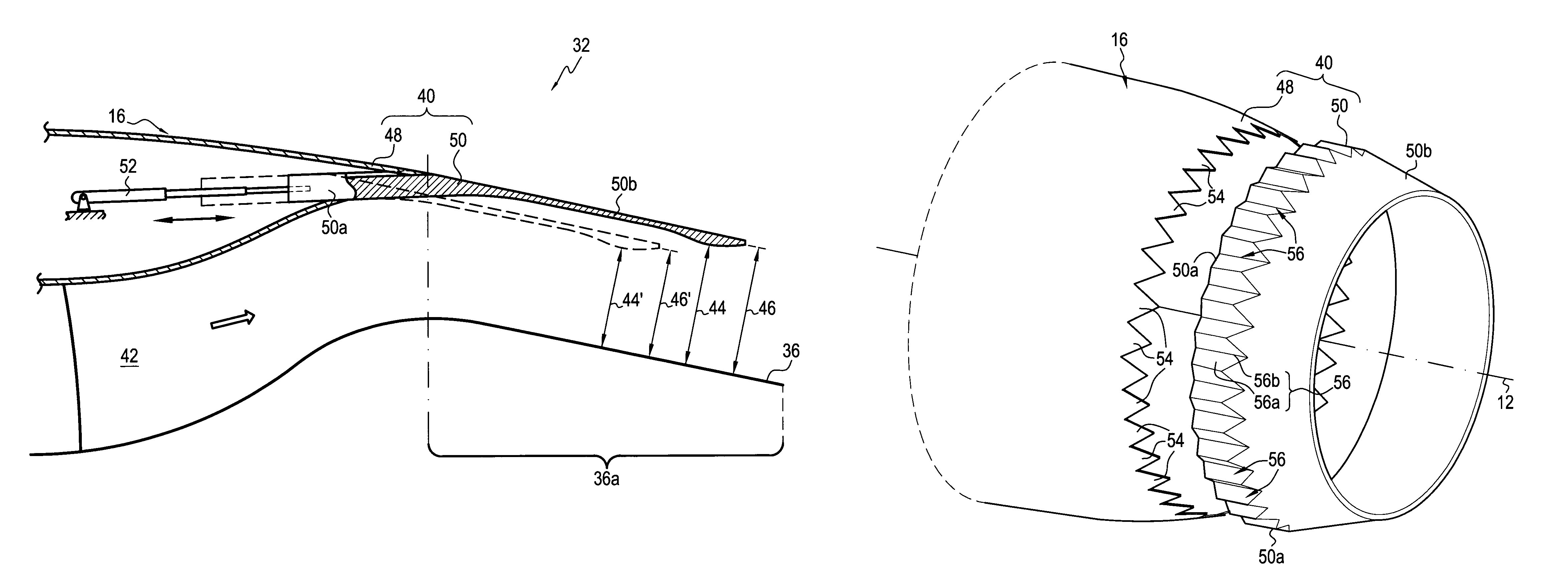
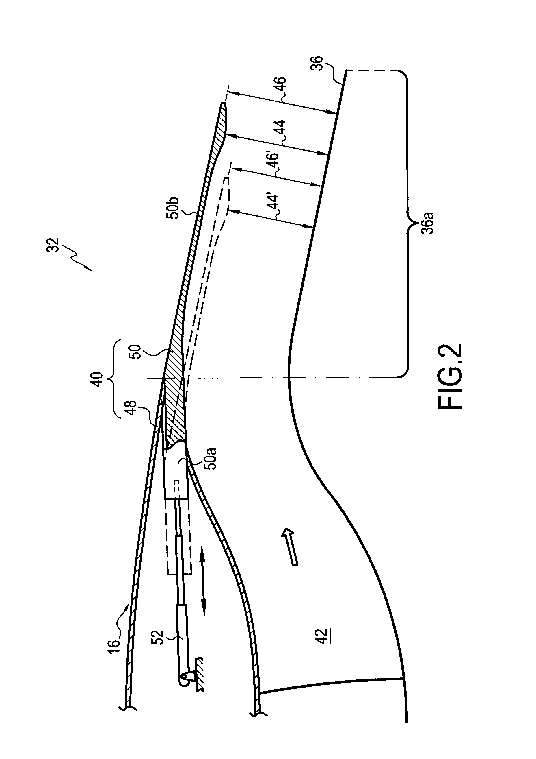
[0020]The nozzle 32 for exhausting the gas produced by such a turbomachine comprises an annular central body 34 centered on the longitudinal axis 12 of the turbomachine, an annular primary cowl 36 coaxially surrounding the central body to co-operate therewith to define a primary annular channel 38, ...


PUM


Abstract

The invention relates to an exhaust nozzle for a bypass turbomachine, the nozzle comprising a central body, a primary cowl surrounding the central body to define a primary channel, and a secondary cowl surrounding the primary cowl to define a secondary annular channel, the secondary cowl comprising a stationary portion and a movable portion disposed to extend the stationary portion and capable of moving longitudinally upstream and downstream relative to the stationary portion and relative to the primary cowl so as to vary the exhaust section and / or the throat section of the nozzle, the stationary portion of the secondary cowl presenting a plurality of spaced-apart repetitive patterns disposed extending its trailing edge, and the movable portion of the secondary cowl including in its outside surface a plurality of indentations of shapes complementary to the patterns of the stationary portion.

Description

BACKGROUND OF THE INVENTION[0001]The present invention relates to the general field of gas exhaust nozzles for bypass turbomachines, and more particularly to a turbomachine nozzle having an exhaust or throat section that is variable as a function of operating speed.[0002]A bypass turbomachine nozzle typically comprises an annular central body centered on a longitudinal axis of the nozzle, an annular primary cowl coaxially surrounding the central body to co-operate therewith to define a primary annular channel, and an annular secondary cowl coaxially surrounding the primary cowl to co-operate therewith to define a secondary annular channel coaxial about the primary channel.[0003]The term “nozzle throat section” is used to designate the cross-section of the secondary channel that is the smallest along the entire length of the nozzle. The term “nozzle exhaust section” is used to designate the cross-section of the secondary channel that is the furthest downstream.[0004]It is known that ...

Claims


Application Information

Patent Timeline
Patent Type & Authority Patents(United States)
IPC IPC(8): F02K1/00
CPCF02K1/09F02K1/386F02K3/06F02K1/72F05D2250/183Y02T50/671Y02T50/60
Inventor CHANEZ, PHILIPPE GERARDZEGGAI, KAMEL
Owner SN DETUDE & DE CONSTR DE MOTEURS DAVIATION S N E C M A
Why Eureka
Try Eureka