Conductive contact for CPU socket connector

a technology of conductive contact and socket connector, which is applied in the direction of coupling contact members, fixed connections, coupling device connections, etc., can solve the problems of high cost, high efficiency, time-consuming, etc., and achieve the effect of low cost and high efficiency

Inactive Publication Date: 2009-10-13
HON HAI PRECISION IND CO LTD
View PDF11 Cites 12 Cited by
  • Summary
  • Abstract
  • Description
  • Claims
  • Application Information

AI Technical Summary

Benefits of technology

[0006]Accordingly, an object of the present invention is to provide a conductive contact with lower cost and high efficiency to make.
[0007]In order to achieve the above-mentioned object, a conductive contact adapted for electrically connecting with a chip module and a printed circuit board comprises a base portion, a top head portion formed above the base portion adapted for connecting with a belt, at least one spring arm extending sidewardly from the base portion and forming at least one contacting section adapted for elastically contacting with the chip module, and a bottom soldering portion extending form at least one of the base portion and the spring arm adapted for being soldered to the printed circuit board. The head portion defines a cutout recessed downwardly from a top edge thereof to reduce connecting length between the head portion and the belt and reduce siphonic effect when plating the spring arm.

Problems solved by technology

Gold is very expensive, how to overcome this problem is a question.
How to separate the contacts 100 from the belt conveniently, time-consuming and of high efficiency is another problem needed to be solved.

Method used


Image

  • Conductive contact for CPU socket connector
  • Conductive contact for CPU socket connector
  • Conductive contact for CPU socket connector

Examples


Embodiment Construction

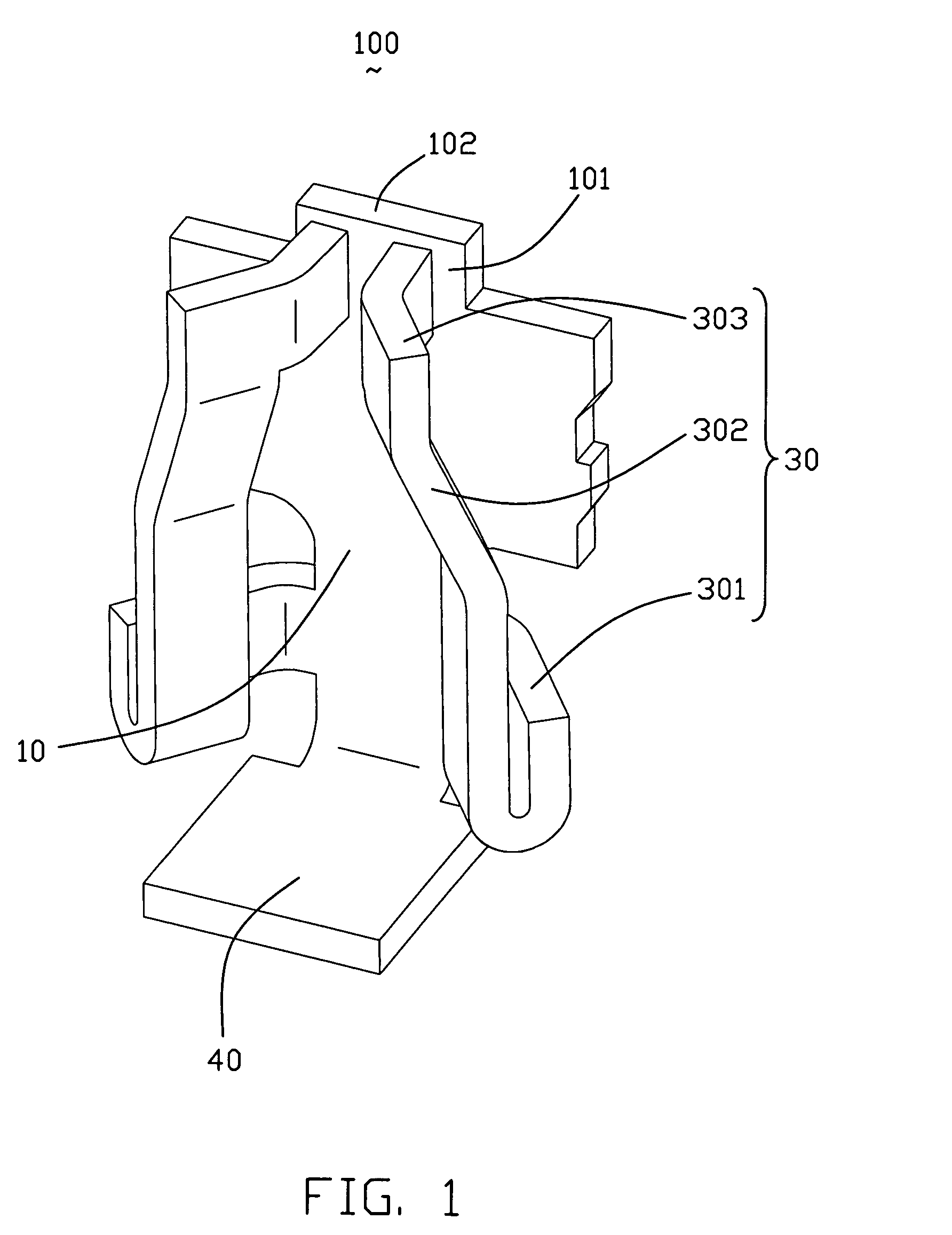
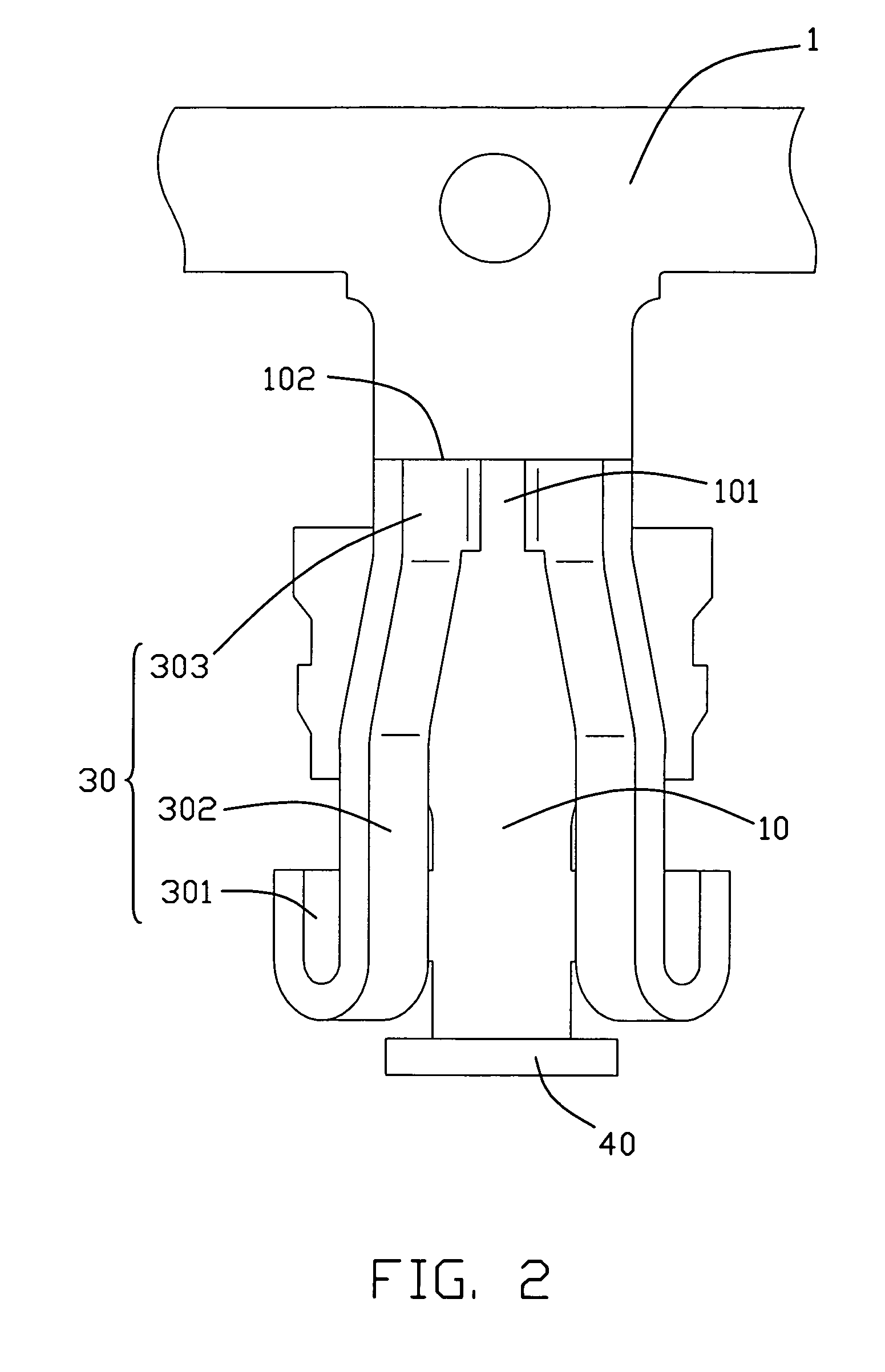
[0014]Reference will now be made to the drawing figures to describe the present invention in detail.

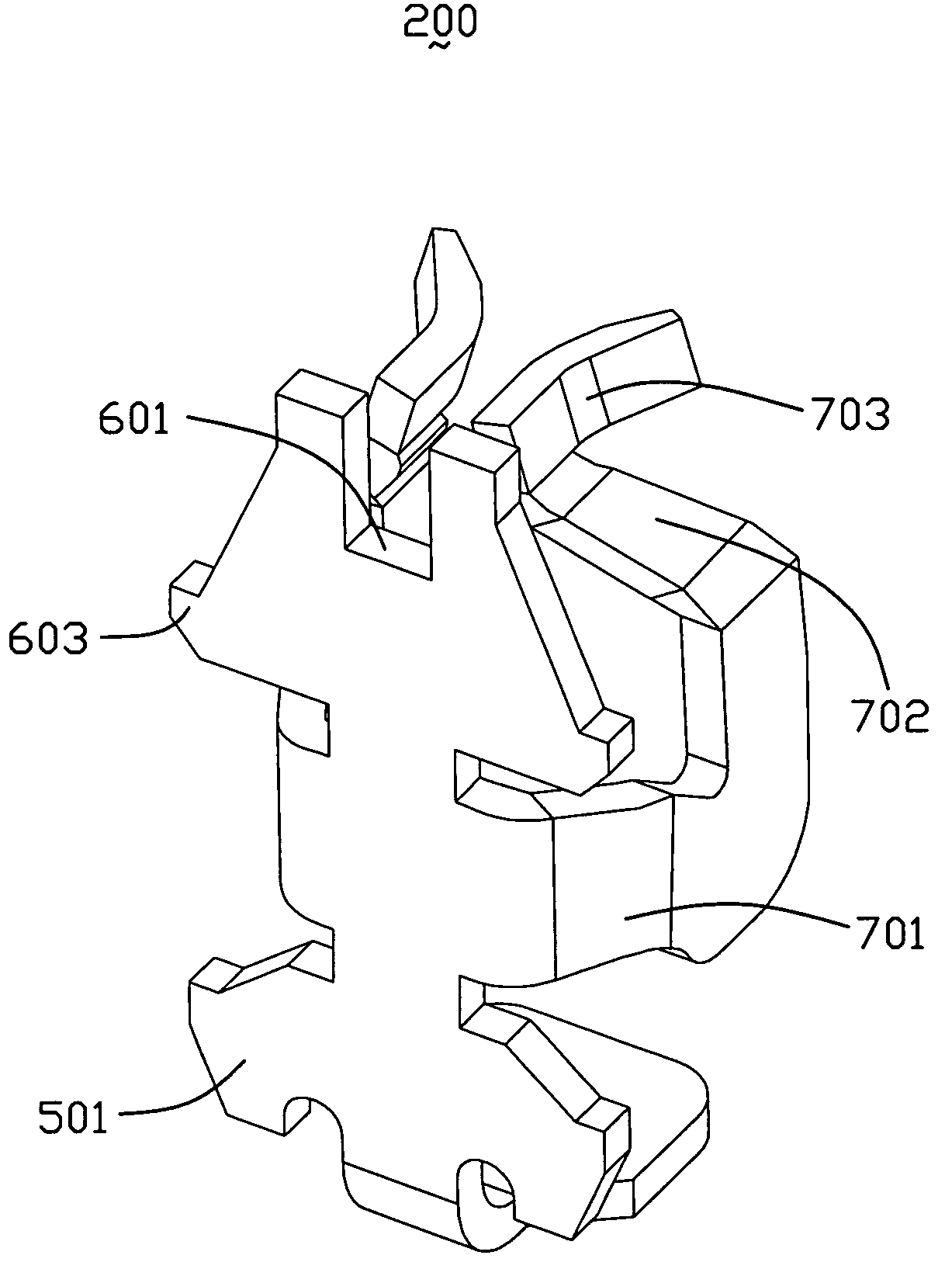
[0015]Please refer to FIGS. 1-5, a conductive contact 200 in accordance with the present invention is used for electrically connecting a chip module, such as a CPU (Central Processing Unit), to a PCB (Printed Circuit Board). The conductive contact 200 comprises a base 50, a head portion 60 located above the base 50 and coplanarly connected with the base 50, a pair of spring arms 70 extending forwardly from middle lateral sides of the base 50 and a bottom flat soldering portion 80 perpendicular to the base 50 and connecting with the base 50 via a curved neck 90. The soldering portion 80 is located below the pair of spring arms 70.

[0016]The head portion 60 is of trapeziform-shape and defines a U-shape cutout 601 downwardly recessed from a top edge 602 thereof, thus, the top edge 602 is divided by the cutout 601 into two sections which serve as connecting part of the conductive contact 2...


PUM


Abstract

A conductive contact (200) for electrically connecting with a chip module and a printed circuit board comprises a base portion (50), a top head portion (60) formed above the base portion adapted for connecting with a belt, at least one spring arm (70) extending sidewardly from the base portion and forming at least one contacting section (703) adapted for elastically contacting with the chip module, and a bottom soldering portion (80) extending form at least one of the base portion and the spring arm adapted for being soldered to the printed circuit board. The head portion defines a cutout (601) recessed downwardly from a top edge (602) thereof to reduce connecting length between the head portion and the belt and reduce siphonic effect when plating the spring arm.

Description

BACKGROUND OF THE INVENTION[0001]1. Field of the Invention[0002]The present invention generally relates to a conductive contact for an electrical connector, and more particularly to a conductive contact for a CPU (Central Processing Unit) socket connector.[0003]2. Description of Related Art[0004]Conductive contacts accommodated in a CPU socket connector for electrically connecting a CPU with a PCB (Printed circuit board) usually comprises a base, at least one arm extending from opposite sides of the base, at least one contacting section formed at free end of the at least one arm for electrically connecting with the CPU and a soldering section extending from the base for electrically connecting with the PCB. The arm comprises a stretching section and a connecting section connecting the stretching section with the contacting section. When in use, the pins of the CPU are inserted into spaces formed by the arms of the conductive contacts and contact the contacting sections of the conduc...

Claims


Application Information

Patent Timeline
Patent Type & Authority Patents(United States)
IPC IPC(8): H01R11/22H01R12/55
CPCH01R12/716H01R13/11H01R12/57
Inventor CHENG, CHIH-PIMA, HAO-YUN
Owner HON HAI PRECISION IND CO LTD
Why Eureka
Try Eureka