Multi-density skin marker

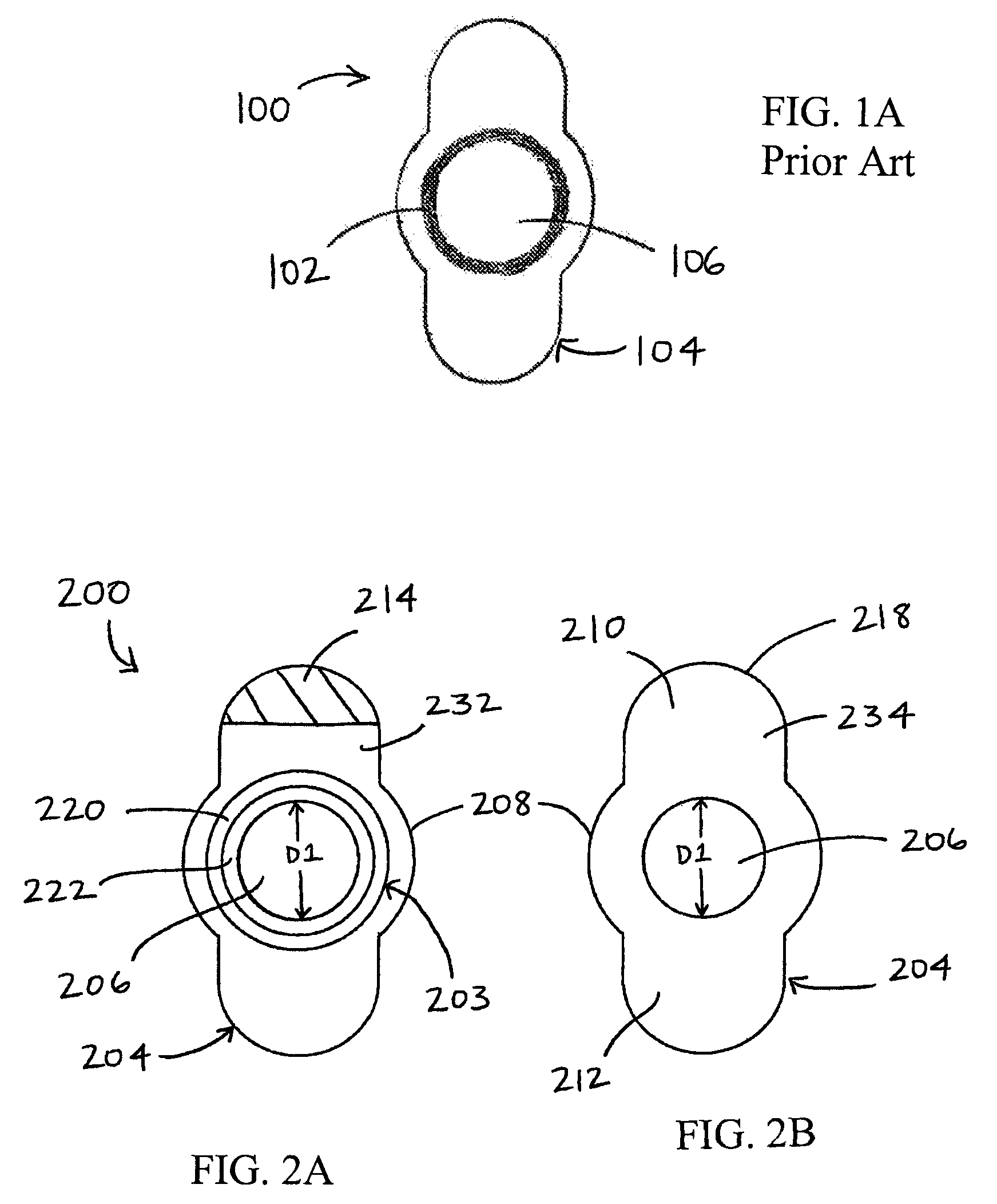
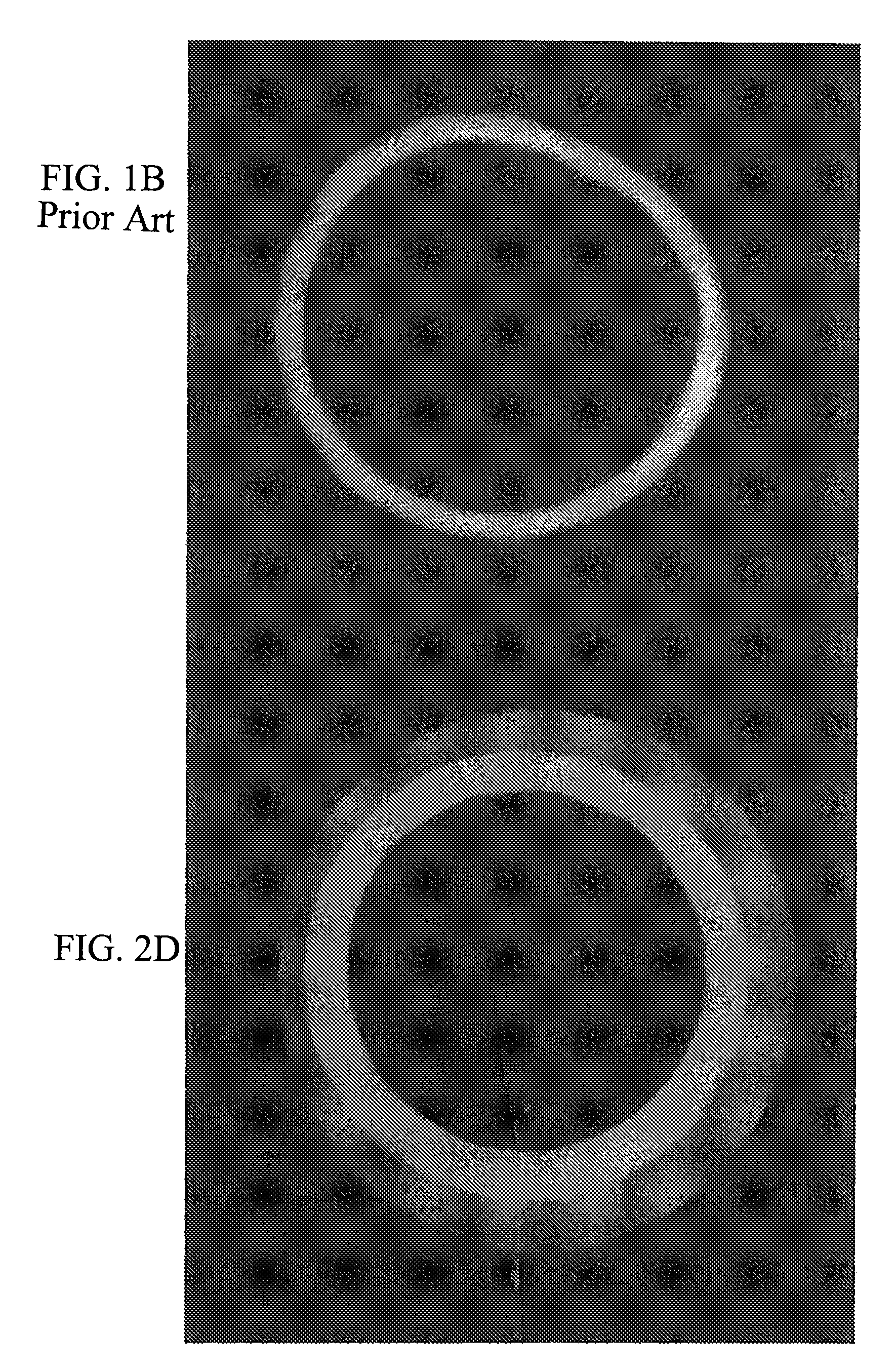
a skin marker and multi-density technology, applied in the field of skin markers for medical imaging exams, can solve the problems of radiolucent skin markers that cannot register on the radiographic image, radiolucent skin markers can also fail to provide a three-dimensional perspective on the resulting image, and relatively flat markers with no change in thickness can also fail to add depth to an imag

Active Publication Date: 2009-10-13
PRECISION DYNAMICS CORPORATION
View PDF19 Cites 14 Cited by
  • Summary
  • Abstract
  • Description
  • Claims
  • Application Information

AI Technical Summary

Problems solved by technology

Radiolucent skin markers can fail to register on the radiographic image, especially when the x-ray or other exam is used to image very dense tissue, such as dense breast tissue.
Radiolucent skin markers can also fail to provide a three-dimensional perspective on the resulting image.
A relatively flat marker with no change in thickness can also fail to add depth to an image.

Method used


Image

  • Multi-density skin marker
  • Multi-density skin marker
  • Multi-density skin marker

Examples


Embodiment Construction

[0028]The detailed description set forth below in connection with the appended drawings is intended as a description of the presently preferred embodiments of a multi-density skin marker provided in accordance with the present invention and is not intended to represent the only forms in which the present invention may be constructed or utilized. The description sets forth the features of the present invention in connection with the illustrated embodiments. It is to be understood, however, that the same or equivalent functions and structures may be accomplished by different embodiments that are also intended to be encompassed within the spirit and scope of the invention. As denoted elsewhere herein, like element numbers are intended to indicate like elements or features.

[0029]The present invention relates to skin markers for medical imaging exams, and more particularly to multi-density skin markers for medical imaging exams. The skin marker contains a multi-density imaging body havin...


PUM


Abstract

A multi-density skin marker for medical imaging exams is provided. The skin marker contains a multi-density imaging body. In one embodiment, a multi-density skin marker includes a marker substrate and a multi-density imaging body supported by the marker substrate. The multi-density imaging body comprises a first portion having a first radiographic density and a second portion having a second radiographic density. The two radiographic densities differ, such that a radiographic image of the multi-density skin marker comprises a plurality of shades.

Description

FIELD OF THE INVENTION[0001]The present invention relates to skin markers for medical imaging exams, and more particularly to multi-density radiolucent skin markers for medical imaging exams.BACKGROUND OF THE INVENTION[0002]Radiolucent skin markers are often used in the medical profession to identify particular areas of interest on a patient for a medical imaging exam. A small marker with a radiolucent or semiopaque imaging body can be adhered to the patient's skin next to or near the area of interest, such as a skin protrusion or lesion or a mass below the skin. An example of a prior art skin marker 100 is shown in FIG. 1A. The marker 100 includes a marker substrate 104 with a central opening 106 and an imaging body 102. In FIG. 1A, the imaging body 102 is shaped as a ring that encircles the central opening 106. The marker 100 may be adhered to a patient's skin such that the area of interest is encircled by the imaging ring 102. Other prior art markers include imaging bodies with o...

Claims


Application Information

Patent Timeline
Patent Type & Authority Patents(United States)
IPC IPC(8): H05G1/28
CPCA61B5/6842A61B6/04A61B19/54A61B6/469A61B2019/5404A61B6/502A61B2090/3904A61B90/39
Inventor JOSEPH, KARENPRESS, ADAMSUTTON, FALCON
Owner PRECISION DYNAMICS CORPORATION
Why Eureka
Try Eureka