Female USB connector

Inactive Publication Date: 2009-10-20
U D ELECTRONIC CORP
View PDF2 Cites 27 Cited by
  • Summary
  • Abstract
  • Description
  • Claims
  • Application Information

AI Technical Summary

Benefits of technology

[0008]The present invention has been accomplished under the circumstances in view. It is one object of the present invention to provide a

Problems solved by technology

However, due to limited internal space, it is difficult to install a row of extra metal terminals in the electrically insulative base member A. Further, when a big number of metal terminals

Method used


Image

  • Female USB connector
  • Female USB connector
  • Female USB connector

Examples


Example

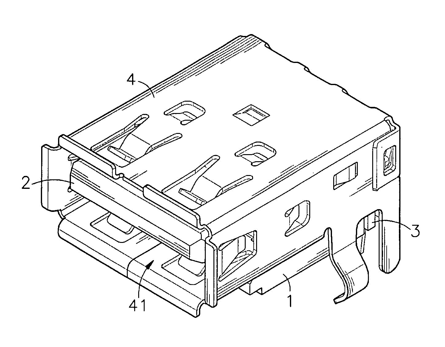
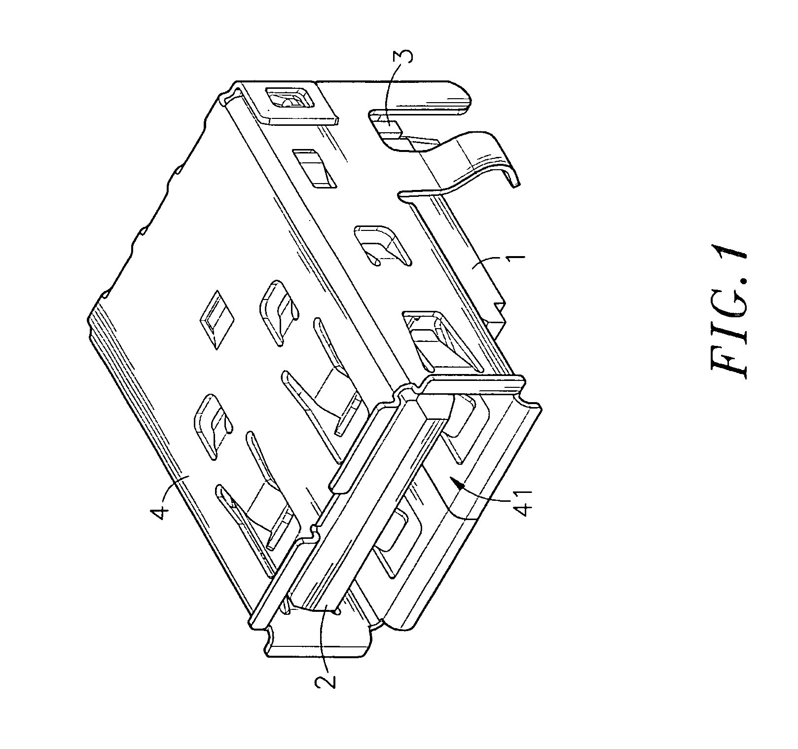
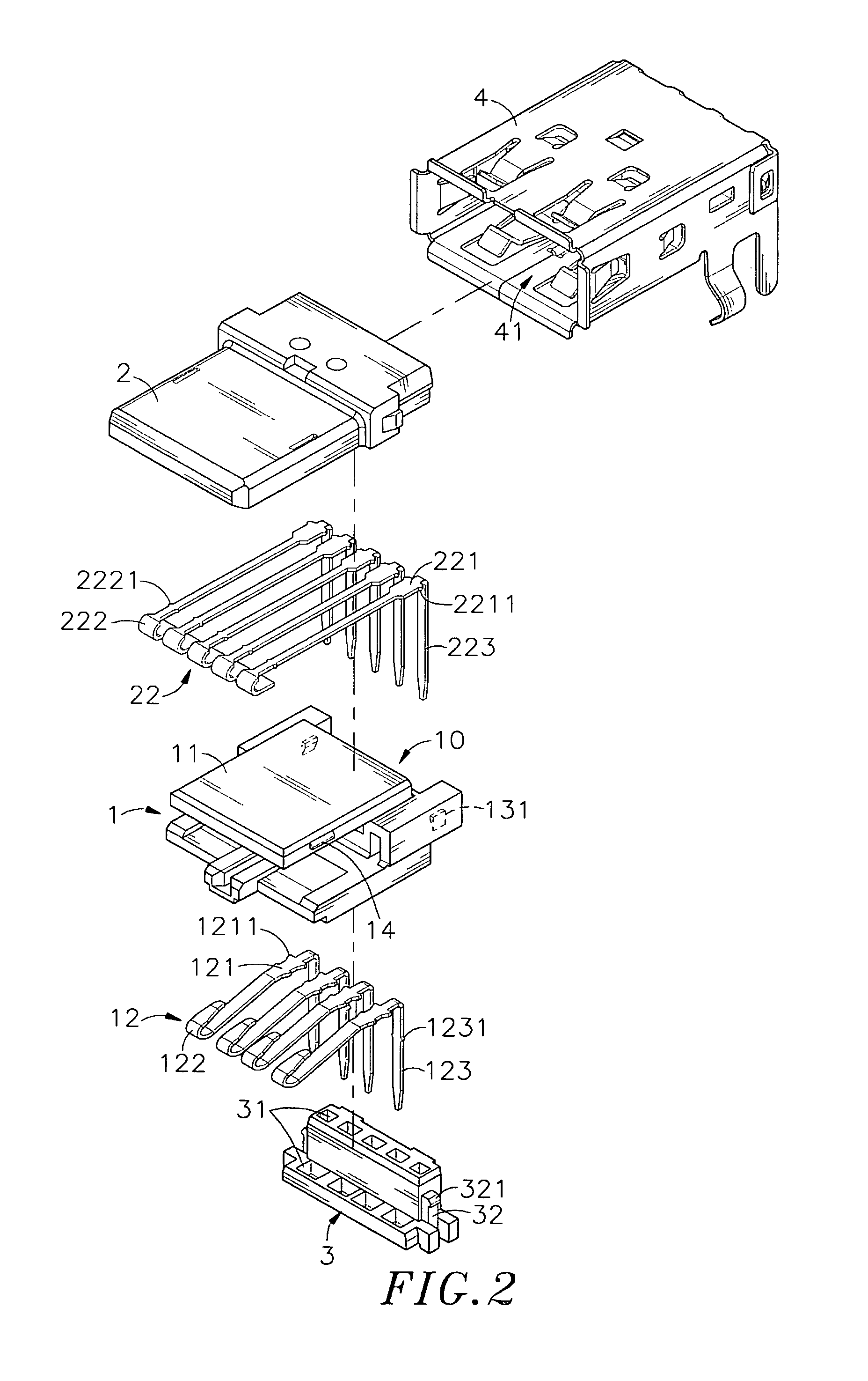
[0019]Referring to FIGS. 1˜4, a female USB connector in accordance with the present invention is shown comprising an electrically insulative base member 1, a set of first metal terminals 12, an electrically insulative tongue plate 2, a set of second metal terminals 22, an electrically insulative terminal holder block 3, and a metal shielding shell 4.

[0020]The electrically insulative base member 1 comprises an abutment portion 11, a terminal holder block positioning space 10 defined in a rear side of the abutment portion 11, a plurality of horizontal terminal grooves 111 formed inside the abutment portion 11 in a parallel manner, a plurality of vertical terminal grooves 112 formed in the rear side of the abutment portion 11 in a parallel manner and respectively downwardly extending from the rear ends of the horizontal terminal grooves 111, two locating grooves 13 formed in the rear side of the abutment portion 11 and symmetrically disposed at two opposite lateral sides relative to th...


PUM


Abstract

A high stability and EMI protective female USB connector is disclosed to include an electrically insulative base member, which holds a set of first metal terminals in a top abutment portion thereof and has two locating blocks at two sides of the top abutment portion, an insulative tongue plate, which holds a set of second metal terminals and has a bottom accommodation space that accommodates the top abutment portion of the insulative base member and two hook blocks disposed at two sides and respectively hooked up with the locating blocks of the insulative base member, an insulative terminal holder block fastened to the rear side of the insulative base member to hold the rear bonding portions of the first and second metal terminals in an array, and a metal shielding shell surrounding the insulative base member and the insulative tongue plate for grounding to provide excellent EMI protection.

Description

BACKGROUND OF THE INVENTION[0001]1. Field of the Invention[0002]The present invention relates to USB (Universal Serial Bus) connectors and more particularly, to a female USB connector, which has a set of first metal terminals and a set of second metal terminals respectively mounted in an electrically insulative base member and an electrically insulative tongue plate to avoid signal transmission interference. The electrically insulative base member and the electrically insulative tongue plate are fastened together by means of a hook joint, simplifying installation.[0003]2. Description of the Related Art[0004]Following fast development of modern electronic technology, advanced consumer electronic products have been continuously created and are intensively used in our daily living for different applications. Nowadays, people use a portable notebook to substitute for a deck computer. These advanced electronic products may use a transmission cable for transmitting photos, files, programs...

Claims


Application Information

Patent Timeline
IPC IPC(8): H01R24/00
CPCH01R13/5045H01R13/65802H01R12/716H01R12/724H01R13/6582
Inventor CHEN, PO-JUNG
Owner U D ELECTRONIC CORP
Why Eureka
Try Eureka