Kinematic images formed by orienting alignable flakes
What is AI technical title?
AI technical title is built by Patsnap AI team. It summarizes the technical point description of the patent document.
a technology of alignable flakes and kinematic images, applied in the field of kinematic images, can solve the problems of limited invention, difficult copying, and unfavorable identification of optically variable devices intended to be noticed, and achieve the effect of easy identification and difficult counterfeiting
Active Publication Date: 2009-10-20
VIAVI SOLUTIONS INC
View PDF112 Cites 42 Cited by
Summary
Abstract
Description
Claims
Application Information
AI Technical Summary
This helps you quickly interpret patents by identifying the three key elements:
Problems solved by technology
Method used
Benefits of technology
Benefits of technology
[0035]The image in accordance with this invention is difficult to counterfeit, visually appealing, easily identifiable and is particularly useful as a security feature or a decorative feature.
Problems solved by technology
Unfortunately, some optically variable devices that are intended to be noticed are not widely known because the optically variable aspect of the device is not sufficiently dramatic.
Although the rolling bar described in the aforementioned PCT patent application provides the illusion of a moving bar across a rectangular image, this invention has limitations.
It is also somewhat difficult to copy.
Method used
Image
Click on the blue label to locate the original text in one second.
Reading with bidirectional positioning of images and text.
Examples
Embodiment Construction
I. Introduction
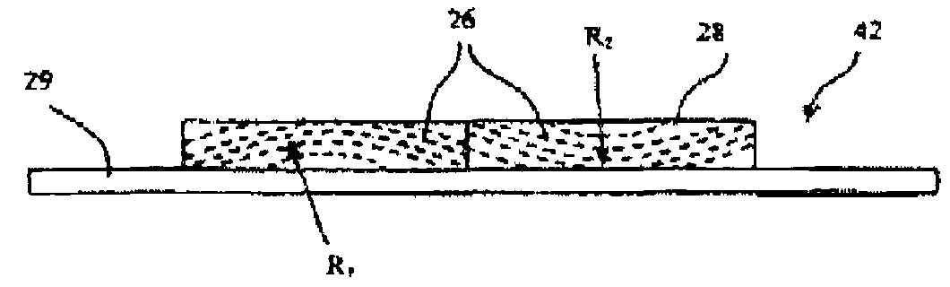
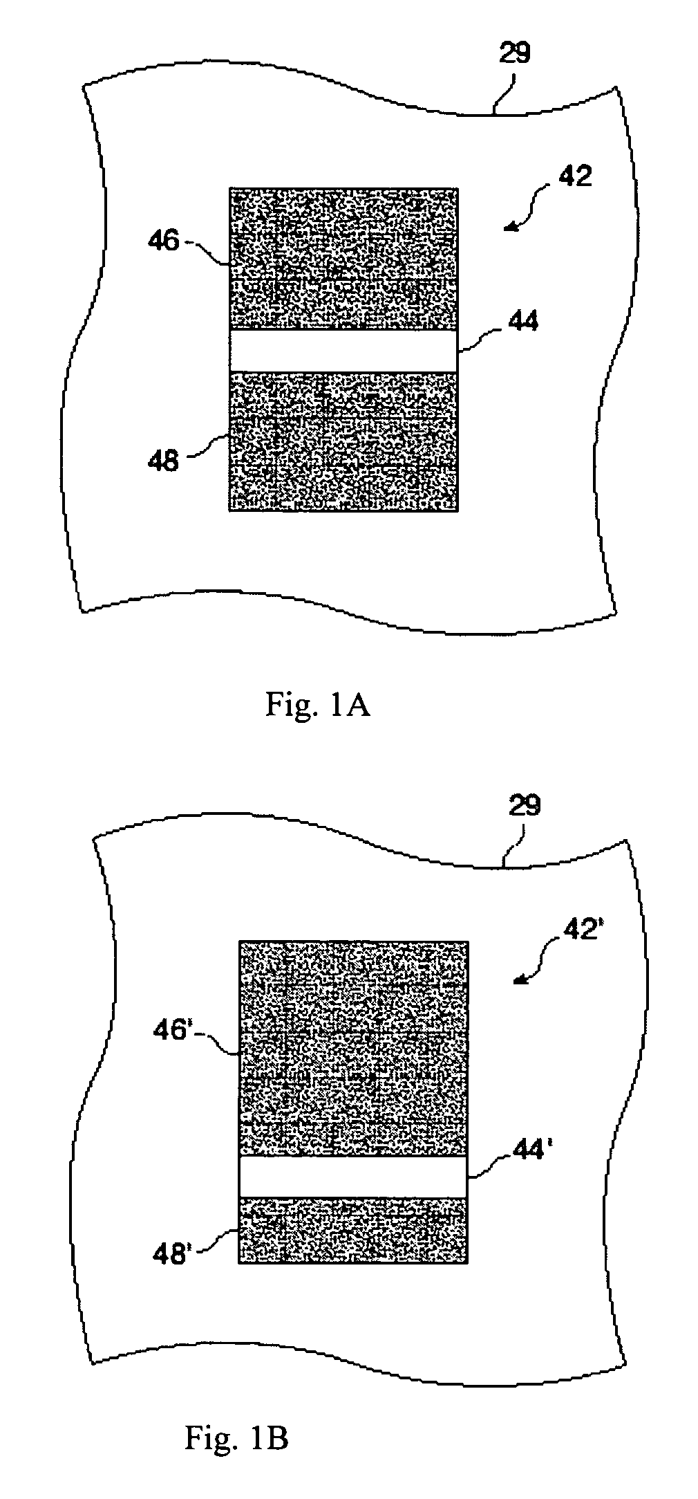
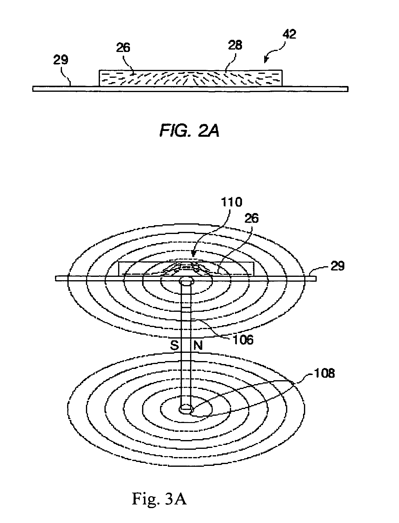
[0073]The present invention in its various embodiments provides methods of orientation of magnetic flakes of optically variable ink or paint suitable in some embodiments as a high-speed printing process wherein other embodiments are more suited to a manual alignment and printing process. In addition, some embodiments of this invention require a multi-step printing process wherein a first region of a substrate is inked with magnetic flakes and exposed to a magnetic field, and wherein after curing, the same substrate is inked in a same or different region and exposed to a second magnetic field. Normally, particles of an optically variable pigment dispersed in a liquid paint or ink vehicle generally orient themselves parallel to the surface when printed or painted on to a surface. Orientation parallel to the surface provides high reflectance of incident light from the coated surface. Magnetic flakes can be tilted while in the liquid medium by applying a magnetic field. T...
PUM
Property
Measurement
Unit
thick
aaaaa
aaaaa
thick
aaaaa
aaaaa
angle
aaaaa
aaaaa
Abstract
An image is disclosed comprised of flakes in a carrier, such as an ink vehicle or a paint that can be aligned in a magnetic field. The flakes are aligned so as to produce one or more kinematic features such as a rolling bar that appears to move as the image is tilted. These images can provide security features on high-value documents, such as bank notes.
Description
CROSS-REFERENCE TO RELATED APPLICATIONS[0001]This patent application is a continuation-in-part and claims priority from U.S. patent application Ser. No. 11 / 022,106, now U.S. Pat. No. 7,517,578, filed Dec. 22, 2004, which claims priority from U.S. patent application Ser. No. 10 / 386,894 filed Mar. 11, 2003, now issued U.S. Pat. No. 7,047,883, which claims priority from U.S. Provisional Patent Application Ser. No. 60 / 410,546 filed Sep. 13, 2002, by Vladimir P. Raksha; from U.S. Provisional Patent Application Ser. No. 60 / 410,547 filed Sep. 13, 2002 by Vladimir P. Raksha, Paul G. Coombs, Charles T. Markantes, Dishuan Chu, and Jay M. Holman; and from U.S. Provisional Patent Application Ser. No. 60 / 396,210 filed Jul. 15, 2002 by Vladimir P. Raksha, Paul C. Coombs, Charles T. Markantes, Dishuan Chu, and Jay M. Holman, the disclosures of which are hereby incorporated in their entirety for all purposes.BACKGROUND OF THE INVENTION[0002]This invention relates generally to optically variable pig...
Claims
Application Information
Patent Timeline
Application Date:The date an application was filed.
Publication Date:The date a patent or application was officially published.
First Publication Date:The earliest publication date of a patent with the same application number.
Issue Date:Publication date of the patent grant document.
PCT Entry Date:The Entry date of PCT National Phase.
Estimated Expiry Date:The statutory expiry date of a patent right according to the Patent Law, and it is the longest term of protection that the patent right can achieve without the termination of the patent right due to other reasons(Term extension factor has been taken into account ).
Invalid Date:Actual expiry date is based on effective date or publication date of legal transaction data of invalid patent.

