Piezoelectric device

a piezoelectric ceramic and piezoelectric technology, applied in the direction of basic electric elements, electrical apparatus, printing, etc., can solve the problems of difficult to achieve piezoelectric characteristics, and compositions of the existing pzt piezoelectric ceramics disclosed in the prior, and achieves easy oxidation, suppresses copper oxidation, and increases piezoelectric constant

Active Publication Date: 2009-10-20
MURATA MFG CO LTD
View PDF9 Cites 6 Cited by
  • Summary
  • Abstract
  • Description
  • Claims
  • Application Information

AI Technical Summary

Benefits of technology

[0021]In preferred embodiments of the present invention, the average valence of the B sites preferably is adjusted in advance to be larger than 4 so that the donor is in excess. In this manner, even when copper in the electrodes diffuses into the piezoelectric ceramic and dissolves in the B sites, the decrease in average valence due to the copper diffusion can be compensated and the decrease in piezoelectric constant d can be suppressed.
[0041]In the case where nickel is contained in the electrodes, the acceptor element MII should at least contain nickel so that diffusion of nickel in the electrode into the piezoelectric ceramic can be suppressed and the decrease in piezoelectric characteristics can be effectively suppressed. Moreover, as described above, since the donor in the B sites is excessive and nickel diffusing from the electrodes acts as an acceptor once it is dissolved in the B sites, the decrease in average valence of the B sites resulting from diffusion of nickel from the electrodes can be compensated.

Problems solved by technology

In other words, the inventors have discovered that when a base metal material, such as copper, is used as the internal electrode material, copper is oxidized during firing and it is difficult to achieve a piezoelectric characteristic comparable to when Ag—Pd having high oxidation resistance is used as in the related art.
However, the compositions of the existing PZT piezoelectric ceramics disclosed in the prior art documents described above do not take into account such degradation in characteristics caused by diffusion of the internal electrode material into the piezoelectric ceramic.
Thus, it has been difficult to form a piezoelectric device having desired piezoelectric characteristics.

Method used


Image

  • Piezoelectric device
  • Piezoelectric device
  • Piezoelectric device

Examples


example 1

[0096]Powders of Pb3O4, TiO2, ZrO2, NiO, and Nb2O5 were prepared as ceramic raw materials, and predetermined amounts of the ceramic raw materials were weighed and mixed so that compositions shown in Table 1 were obtained. Each mixture was wet-milled for 16 hours and calcined for 2 hours at 850° C. to obtain a calcined powder of a perovskite complex oxide represented by compositional formula (I):

Pb[(Ni1 / 3Nb(2+b) / 3)zTixZr1−x−z]O3  (I)

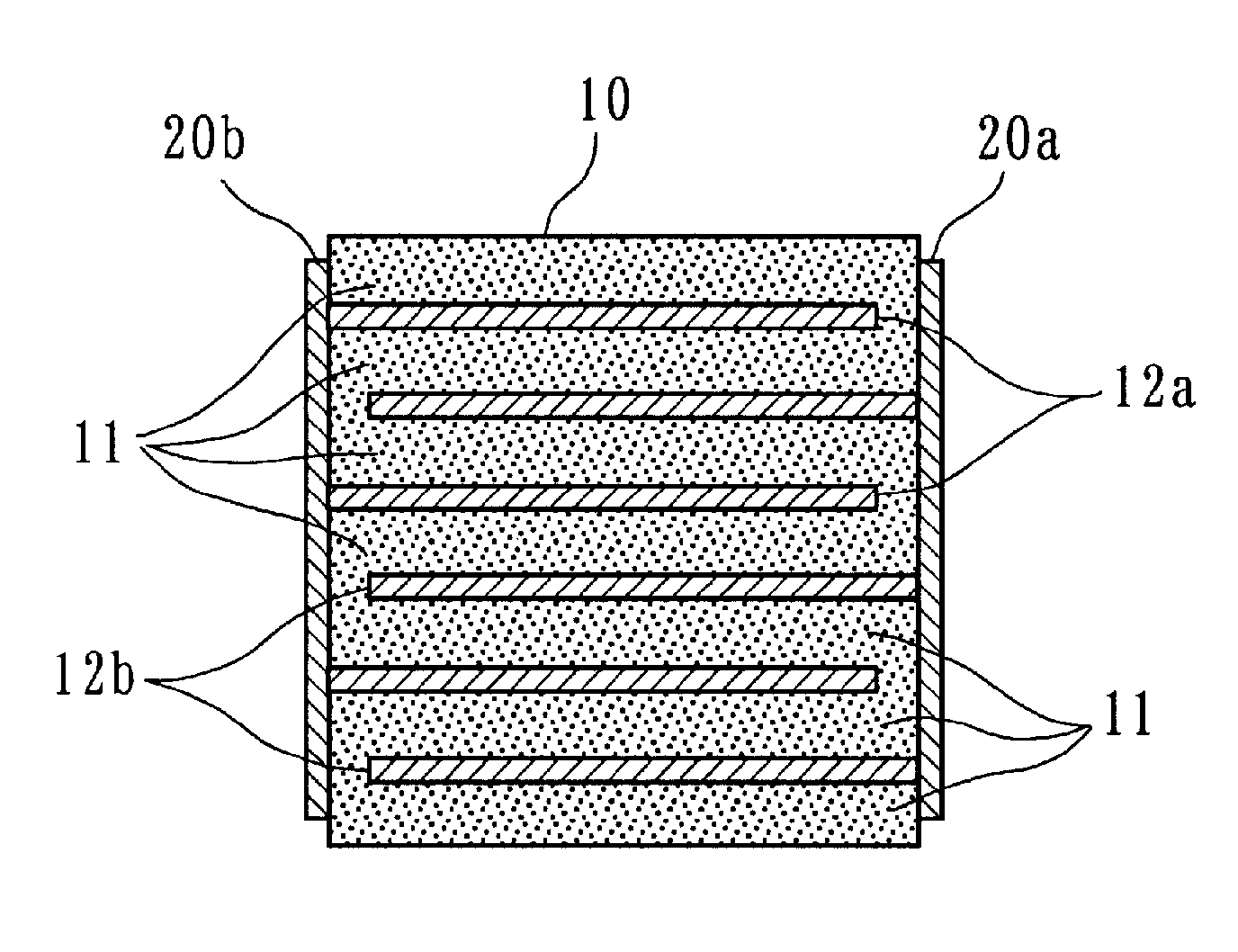
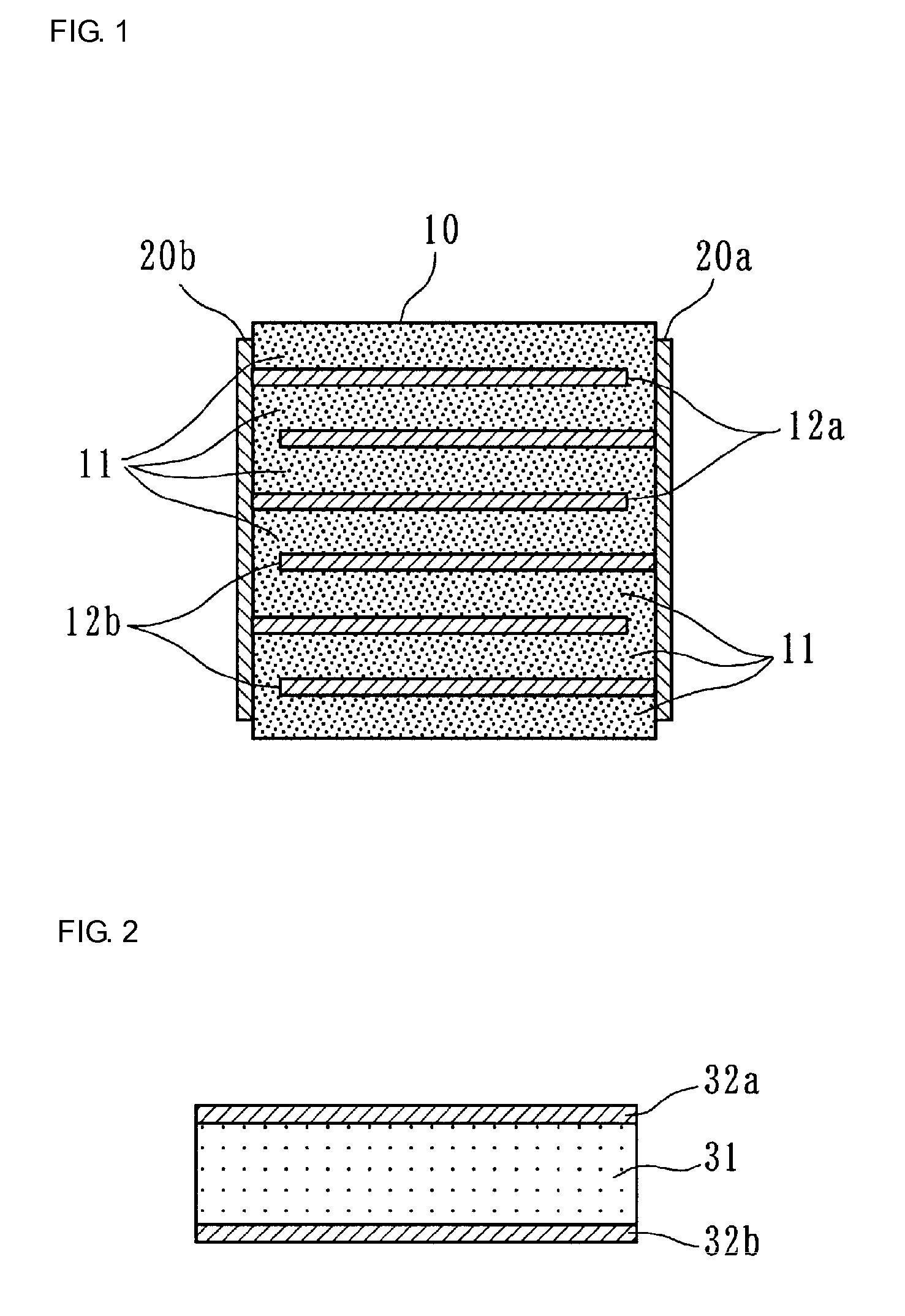
[0097]The resulting calcined powder was mixed with a binder and pure water to obtain a ceramic slurry, and ceramic green sheets having a thickness of 60 μm were prepared by a doctor blade method.

[0098]A conductive paste containing 85 wt % of a copper powder and 15 wt % of a nickel powder was prepared and applied on the ceramic green sheets by screen printing to form conductive layers having predetermined patterns.

[0099]The ceramic green sheets with the conductive layers thereon were stacked in a predetermined direction, and the resulting stack was sandwic...

example 2

[0113]Ceramic raw materials the same as those in Example 1 were used. Predetermined amounts of raw materials were weighed and mixed to prepare compositions shown in Table 2. Each mixture was wet-milled for 16 hours and calcined at 850° C. for 2 hours to obtain a calcined powder composed a perovskite complex oxide represented by formula (IIa):

Pb[(Ni1 / 3Nb(2+b) / 3)zTixZr1−x−z]O3  (IIa)

[0114]In other words, the blend molar ratio α of lead, which is the A-site component, to the B sites was varied, and calcined powders of Sample Nos. 41 to 47 were obtained.

[0115]Piezoelectric devices of Sample Nos. 41 to 47 were then made by the same method and procedure as in Example 1, and the piezoelectric constant d33 and the Curie temperature Tc were measured.

[0116]Table 2 shows the compositions, the piezoelectric constants d33, and the Curie temperatures Tc of Sample Nos. 41 to 47.

[0117]

TABLE 2PiezoelectricCurieSamplePbα(Ni1 / 3Nb(2+b) / 3)ZTixZr1−x−ZO3constant d33temperature TcNo.αbzbz / 3x(pm / V)(°c)41**1...

example 3

[0121]The ceramic raw materials described in Example 1, BaCO3, SrCO3, CaCO3, Nd2O3, and Bi2O3 were prepared, and predetermined amounts of these raw materials were weighed and mixed to obtain compositions shown in Table 3. Each resulting mixture was wet-milled for 16 hours and calcined at 850° C. for 2 hours to obtain calcined powders composed of perovskite complex oxide represented by formula (IIb):

Pb1.000−aMea[(Ni1 / 3Nb2.150 / 3)0.2Ti0.4225Zr0.3775]O3  (IIb)

[0122]In other words, α was set to 1.000, z was set to 0.2, bz / 3 was set to 0.010, x was set to 0.4225, and part of lead in the A sites was substituted with a metal element Me to obtain calcined powders of Sample Nos. 51 to 58.

[0123]Piezoelectric devices of Sample Nos. 51 to 58 were then made by the same method and procedure as in Example 1. Their piezoelectric constants d33 and Curie temperatures Tc were measured.

[0124]Table 3 shows the compositions, the piezoelectric constants d33, and the Curie temperatures Tc of Sample Nos. 51 ...


PUM

PropertyMeasurementUnit
Curie temperature Tcaaaaaaaaaa
molar ratioaaaaaaaaaa
thicknessaaaaaaaaaa

Abstract

A piezoelectric device is formed by simultaneously firing a piezoelectric ceramic mainly composed of a perovskite complex oxide represented by general formula ABO3 and electrodes mainly composed of copper. The piezoelectric ceramic is represented by Pbα−aMea[(MII1 / 3MV(2+b) / 3)zTixZr1−x−z]O3 (wherein Me represe element, MII is an acceptor element which is a divalent metal element, and MV is a donor element which is a pentavalent metal element), and satisfies equations 0.05≦z≦0.40, 0<bz / 3≦0.035, 0.345≦x≦0.480, 0.965≦α≦1.020, and 0≦a≦0.05. In other words, the B sites contain excessive donors, and thus a piezoelectric device having good piezoelectric characteristics can be obtained even in the cases where a base metal material mainly composed of inexpensive copper is used as the internal electrode material.

Description

BACKGROUND OF THE INVENTION[0001]1. Field of the Invention[0002]The present invention relates to piezoelectric devices, in particular, to a piezoelectric device, such as a piezoelectric actuator, including a piezoelectric ceramic containing a perovskite complex oxide as a main component and electrodes containing copper as a main component.[0003]2. Description of the Related Art[0004]Piezoelectric actuators that utilize electrostrictive effects generated by the application of voltage to piezoelectric ceramics are commonly used for alignment of precision machine tools and in print heads of ink jet printers.[0005]A piezoelectric device used as such a piezoelectric actuator is typically fabricated by applying, by printing, a conductive paste on ceramic green sheets containing piezoelectric ceramic powder to form conductive layers, stacking a predetermined number of ceramic green sheets with the conductive layers thereon, simultaneously firing the conductive layers and the ceramic green ...

Claims


Application Information

Patent Timeline
Patent Type & Authority Patents(United States)
IPC IPC(8): H01L41/187B41J2/045B41J2/055B41J2/135B41J2/14C04B35/493H01L41/083H01L41/09H01L41/22H01L41/273H01L41/297
CPCC04B35/493C04B2235/3208C04B2235/3213C04B2235/3215C04B2235/3251C04B2235/3262C04B2235/3279C04B2235/3284C04B2235/3294C04B2235/3298C04B2235/6025C04B2235/6584C04B2235/79H10N30/877H10N30/50H10N30/067H10N30/053H10N30/8554
Inventor YAMAMOTO, ATSUSHIDEGUCHI, YOICHIHAYASHI, KOICHI
Owner MURATA MFG CO LTD
Why Eureka
Try Eureka