Microfluidic valve mechanism

a valve mechanism and microfluidic technology, applied in the field of valves, can solve the problems that the conventional diaphragm valve design is not well suited to regulating and controlling process flow, and achieve the effects of higher thermal melting point, and higher thermal melting poin

Inactive Publication Date: 2009-10-27
MICROFLUIDIC SYST
View PDF6 Cites 93 Cited by
  • Summary
  • Abstract
  • Description
  • Claims
  • Application Information

AI Technical Summary

Problems solved by technology

Conventional diaphragm valve designs are not well suited for regulating and controlling process flows.

Method used


Image

  • Microfluidic valve mechanism
  • Microfluidic valve mechanism
  • Microfluidic valve mechanism

Examples


Embodiment Construction

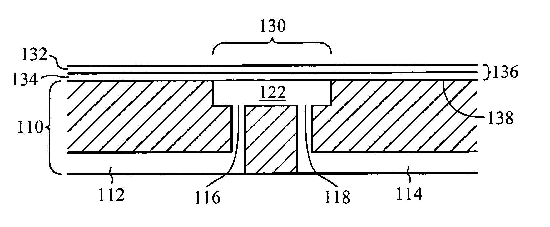
[0023]Embodiments of the present invention are directed to a diaphragm valve integrated as part of a cover of a microfluidic cassette cartridge used in part to transport fluid. Diaphragm valves are used to control fluid flow through the cartridge. The cartridge includes a rigid body portion with a bottom surface and a top surface, a bottom cover positioned over the bottom surface of the body portion, and a top cover positioned over the top surface. The body portion includes a plurality of channels, a first portion of which are referred to as top channels and are disposed along the top surface, a second portion of which are referred to as bottom channels and are disposed along the bottom surface, and a third portion of which are referred to as connecting channels and are disposed from the bottom surface to the top surface. The bottom channels are enclosed except for an open-side facing away from the bottom surface. The top channels are enclosed except for an open side facing away fro...


PUM


Abstract

One or more diaphragm valves are integrated as part of a cover of a microfluidic cassette cartridge. A rigid body portion includes one or more recessed valve areas and a plurality of fluid channels. A recessed valve area is disposed along either a bottom surface or a top surface of the rigid body portion. An inlet fluid channel and an outlet fluid channel are formed within the rigid body portion of each recessed valve area. A flexible membrane cover is sealed over the bottom surface of the body portion, and another flexible membrane cover is sealed over the top surface. A portion of the membrane cover that covers a recessed valve area functions as a valve membrane of the diaphragm valve. The flexible membrane functions as both a cover of the cartridge, thereby sealing and enclosing the appropriate channels, and a valve membrane of the diaphragm valve.

Description

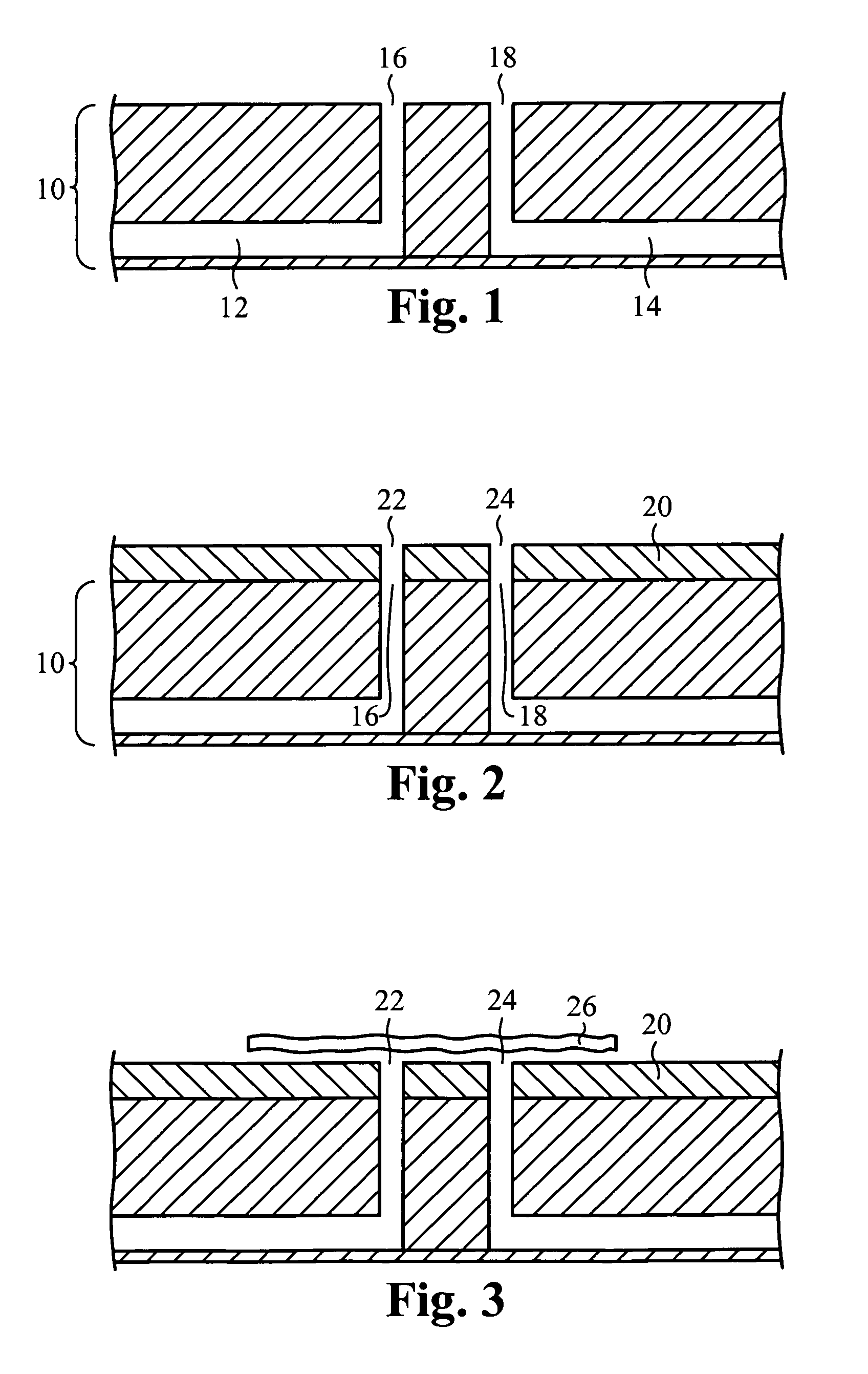
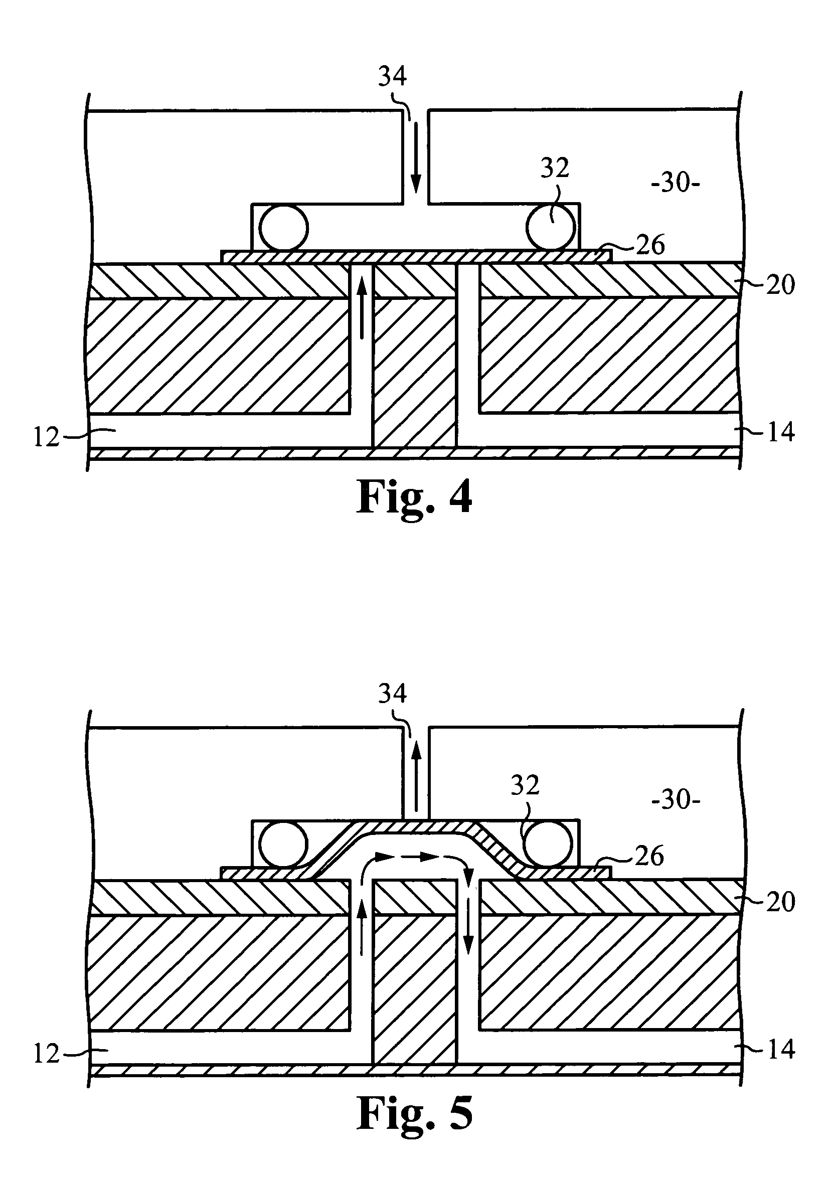
FIELD OF THE INVENTION[0001]The invention relates to a valve. More particularly, the invention relates to valve mechanism applied to microfluidic pathways.BACKGROUND OF THE INVENTION[0002]Conventional diaphragm valves, also referred to as membrane valves, include a valve body with two or more ports, and a flexible membrane which closes the valve. FIG. 1 illustrates an exemplary valve body of a conventional diaphragm valve. The valve body 10 includes an inlet fluid passageway 12 including an inlet end 16, and an outlet fluid passageway 14 including an outlet end 18. A cover 20 (FIG. 2) is coupled to the valve body 10 such that a first opening 22 in the cover 20 is aligned with the inlet end 16, and a second opening 24 in the cover 20 is aligned with the outlet end 16. The valve body 10 and the cover 20 are both made of rigid material. A flexible membrane 26 (FIG. 3) is positioned on the cover 20 such that both the first opening 22 and the second opening 24 are covered. The membrane 2...

Claims


Application Information

Patent Timeline
Patent Type & Authority Patents(United States)
IPC IPC(8): F16K1/00F16K15/00
CPCF16K7/17F16K7/126Y10T137/87249
Inventor YUAN, BOB
Owner MICROFLUIDIC SYST
Why Eureka
Try Eureka