Lighting unit

a technology of light source and light source, which is applied in the direction of fixed installation, lighting and heating equipment, lighting support devices, etc., can solve the problems of difficult to difficult to increase the quantity of light by the plane mirror, and difficult to significantly reduce the size of lighting devices

Inactive Publication Date: 2009-10-27
KOITO MFG CO LTD
View PDF7 Cites 40 Cited by
  • Summary
  • Abstract
  • Description
  • Claims
  • Application Information

AI Technical Summary

Benefits of technology

[0017]One or more embodiments of the invention provide a lighting unit for a vehicle which can switch a light distribution pattern for a low beam and a light distribution pattern for a high beam by means of one projection lens and can form a strong light collecting pattern in an overlap with the low beam without an incompatibility in the high beam.
[0023]According to the lighting unit for a vehicle having the structure, when the tip edge of the cutoff line forming member is positioned on the rear focal point of the projection lens, a part of a light beam emitted from the first light source which passes through the lower part of the rear focal point is intercepted by the tip edge so that a light distribution pattern for a low beam is formed. At this time, a reflected light from the reflector which is to be originally intercepted by the upper surface of the cutoff line forming member is reflected by a reflecting surface provided on the upper surface and is incident on the projection lens. The reflected light is subjected to a conversion control into a low beam emitted downward from the projection lens so that a beam utilization ratio of the light emitted from the first light source can be increased.
[0027]At this time, the reflected light from the reflector which is originally intercepted by the upper surface of the cutoff line forming member is reflected by the reflecting surface provided on the upper surface and is incident on the projection lens. The reflected light is subjected to a conversion control into a low beam emitted downward from the projection lens so that a beam utilization ratio of the light emitted from the first light source can be increased.
[0031]According to the lighting unit having the above structure, in the case in which the upper surface is continuously formed in the shape of the tip edge forming the cutoff line so that the step is formed on the upper surface in the cutoff line forming member in respect of the easiness of manufacture, the light collecting portion is formed by a pair of reflecting surfaces each having a substantially elliptical sphere shape having a focal length varied corresponding to the step. Consequently, a reflected light path distance from one of the reflecting surfaces having a substantially elliptical sphere shape to the reflecting surface in a lower stage of the cutoff line forming member is equal to a reflected light path distance from the other reflecting surface taking the shape of a substantially elliptical sphere to the reflecting surface in an upper stage. Thus, it is possible to form a light collecting pattern having a greater light collection by using the cutoff line forming member which can easily be manufactured.
[0034]Consequently, the tip edge of the cutoff line forming member is separated from the rear focal point, and at the same time, the light emitted from the second light source can be collected in the vicinity of the rear focal point of the projection lens by the reflecting surface of the cutoff line forming member in the separating position. Therefore, the light emitted from the second light source can be collected into the rear focal point of the projection lens by means of one optical element (the reflecting surface taking the shape of a substantially elliptical sphere) and can be then incident on the projection lens. For this reason, it is not necessary to provide other optical elements (a plane mirror and a lens) together. Consequently, it is possible to lessen a strength loss due to a reflection and a light absorption with respect to the light emitted from the second light source.
[0045]Consequently, the light distribution pattern for a low beam and the light distribution pattern for a high beam can be switched by means of a projection lens, and furthermore, it is possible to form a strong light collecting pattern in an overlap with the low beam without an incompatibility in the high beam.

Problems solved by technology

In the vehicle lighting device of the multi-lamp type, however, it is hard to considerably reduce a size of the lighting device.
Therefore, it is necessary to maintain a size in the reflector to some degree and it is hard to reduce a size of the lighting device.
Moreover, when the cutoff line forming member provided on the plane mirror is tilted to form a light distribution pattern for a high beam, it is impossible to increase a quantity of a light by the plane mirror.
Consequently, a maximum quantity of the light is decreased so that a performance of the high beam cannot be satisfied.
In the case in which an LED is used for a light source in order to reduce the size of the lighting device, an insufficient quantity of the light in the high beam becomes more remarkable.
With the structure, however, alight generating the eclipse by the tip of the shade is increased so that a loss is increased.

Method used


Image

  • Lighting unit
  • Lighting unit
  • Lighting unit

Examples


Embodiment Construction

[0057]A lighting unit for a vehicle according to exemplary embodiments of the invention will be described below in detail with reference to the accompanying drawings.

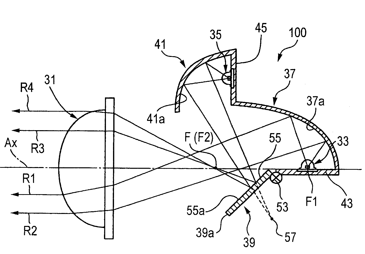
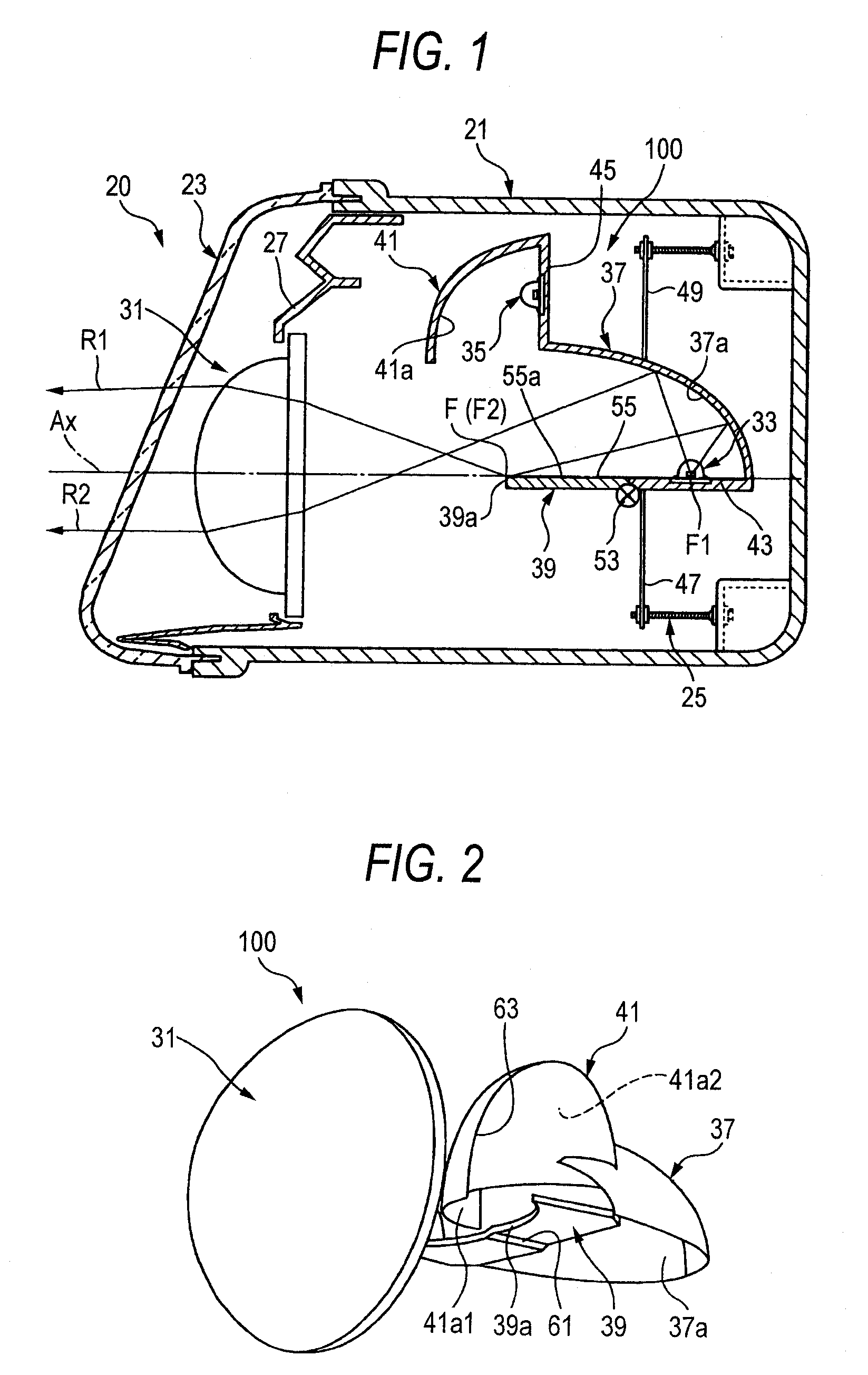
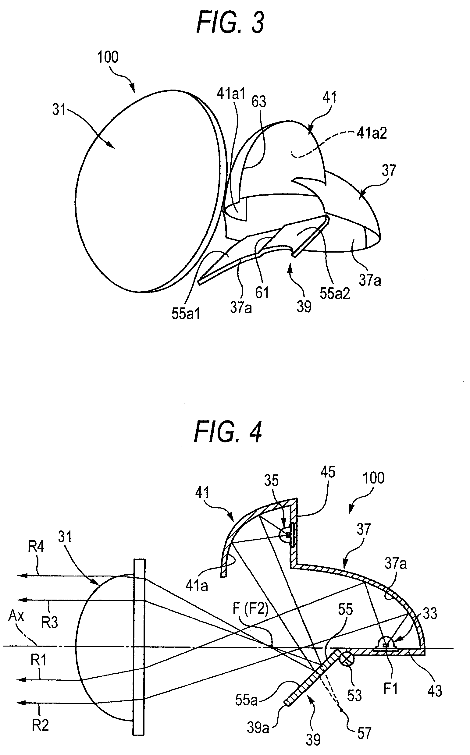
[0058]FIG. 1 is a longitudinal sectional view showing a lighting unit for a vehicle provided with a lighting unit for a vehicle according to a first exemplary embodiment of the invention, FIG. 2 is a perspective view showing an irradiation of a low beam in the lighting unit for a vehicle illustrated in FIG. 1, and FIG. 3 is a perspective view showing an irradiation of a high beam in the lighting unit for a vehicle illustrated in FIG. 1.

[0059]A lighting device 20 according to the first exemplary embodiment is provided with a lamp body 21 formed by a synthetic resin and taking a shape of a container having a front surface side opened, a transparent front cover 23 assembled onto the front opening portion of the lamp body 21 and serving to partition and form a lamp housing S together with the lamp body 21, and a lighting un...


PUM


Abstract

A lighting unit is provided with a cutoff line forming member disposed between a projection lens and a first light source and having a tip edge positioned in a vicinity of a rear focal point of the projection lens. The cutoff line forming member is capable of shielding a part of a light reflected by a reflector, thereby forming a cutoff line of a light distribution pattern for a low beam. An additional reflector is capable of collecting a light emitted from a second light source in a vicinity of the rear focal point of the projection lens. The light emitted from the second light source is collected in the vicinity of the rear focal point of the projection lens in a state in which the tip edge of the cutoff line forming member and the rear focal point of the projection lens are relatively separated from each other, and a light distribution pattern for a high beam is thus formed.

Description

[0001]This application claims foreign priority from Japanese Patent Application No. 2006-304306 filed on Nov. 9, 2006, the entire contents of which are hereby incorporated by reference.BACKGROUND OF THE INVENTION[0002]1. Field of the Invention[0003]The present invention relates to a lighting unit for a vehicle in which a light distribution pattern for a low beam (lower beam) and a light distribution pattern for a high beam (upper beam) can be switched freely.[0004]2. Related Art[0005]Conventionally, some vehicle lighting devices such as headlamps have a structure in which a light distribution pattern for a low beam and a light distribution pattern for a high beam can be switched freely. For example, there has been known a vehicle lighting device of a four-lamp type in which low and high beams are constituted by an LED and a bulb, respectively.[0006]In the vehicle lighting device of the multi-lamp type, however, it is hard to considerably reduce a size of the lighting device.[0007]In...

Claims


Application Information

Patent Timeline
Patent Type & Authority Patents(United States)
IPC IPC(8): F21V7/00
CPCF21S48/1154F21S48/1159F21S48/1163F21S48/1757F21S48/1778F21S48/25F21S48/1388F21Y2101/02F21S41/143F21S41/147F21S41/148F21S41/255F21S41/321F21S41/365F21S41/43F21S41/60F21S41/663F21S41/675F21S41/683F21S41/689F21Y2115/10F21S41/155F21S43/50
Inventor OKADA, NORIKO
Owner KOITO MFG CO LTD
Why Eureka
Try Eureka