
Clip

a technology of clips and clips, applied in the field of clips, can solve the problems of time-consuming and costly installation of other forms of conduit, difficult use of clips, and needing tools and both hands, and achieve the effect of easy securization to a building's structural components and easy and quick securization

Active Publication Date: 2009-10-27
HILL DOUGLAS C
View PDF60 Cites 62 Cited by
  • Summary
  • Abstract
  • Description
  • Claims
  • Application Information

AI Technical Summary

Benefits of technology

"The present invention provides a clips system for securing flexible armored cable and other conduits to building structures. The clip has a base and two side walls that form a cavity for receiving the conduit. The clip can be easily attached to a building's structural components and securely holds the conduit in place. The clip has a unique design that allows for easy and quick attachment of the conduit to the clip. The technical effect of this invention is to provide a simple yet effective solution for securing flexible armored cable and other conduits to building structures."

Problems solved by technology

Likewise, it is also time consuming and costly to install other forms of conduit.
Prior art clips have been created to help secure conduit to the facility; however, these clips are difficult to use, require tools and both hands.
In addition, these prior art clips are costly.

Method used


Image

  • Clip
  • Clip
  • Clip

Examples


Embodiment Construction

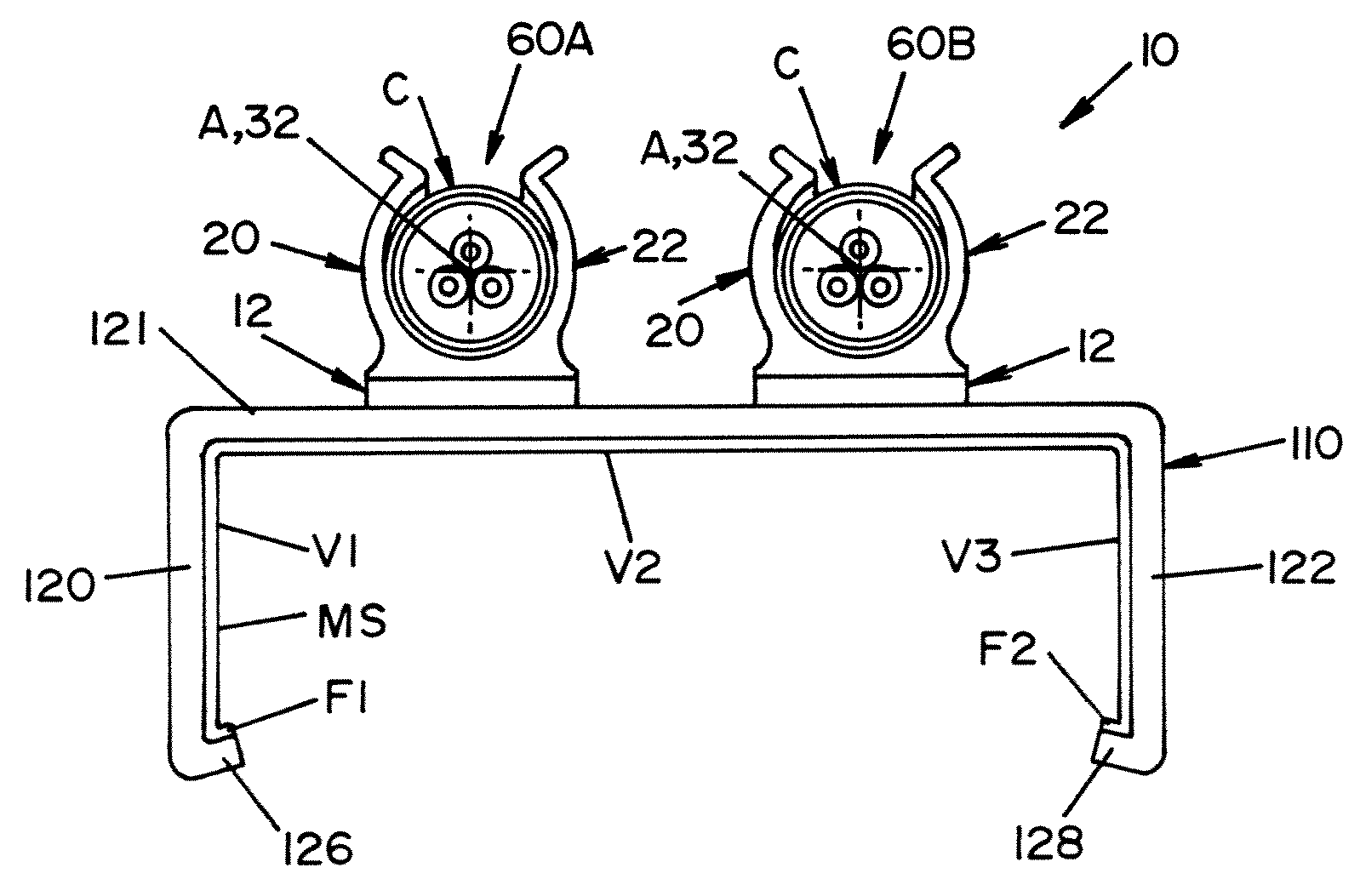
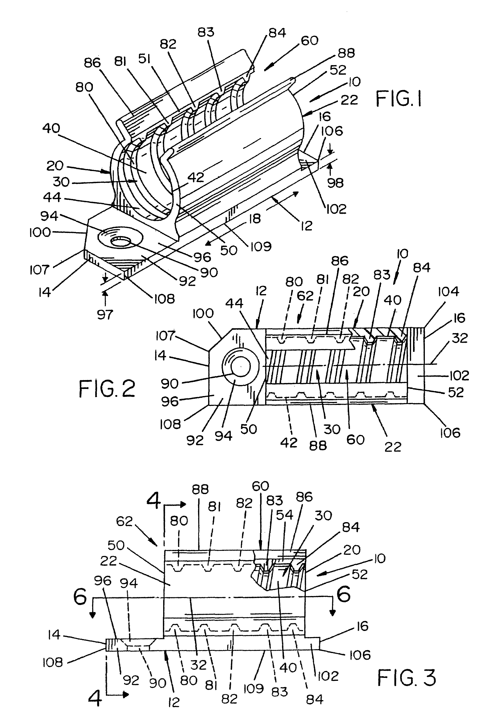
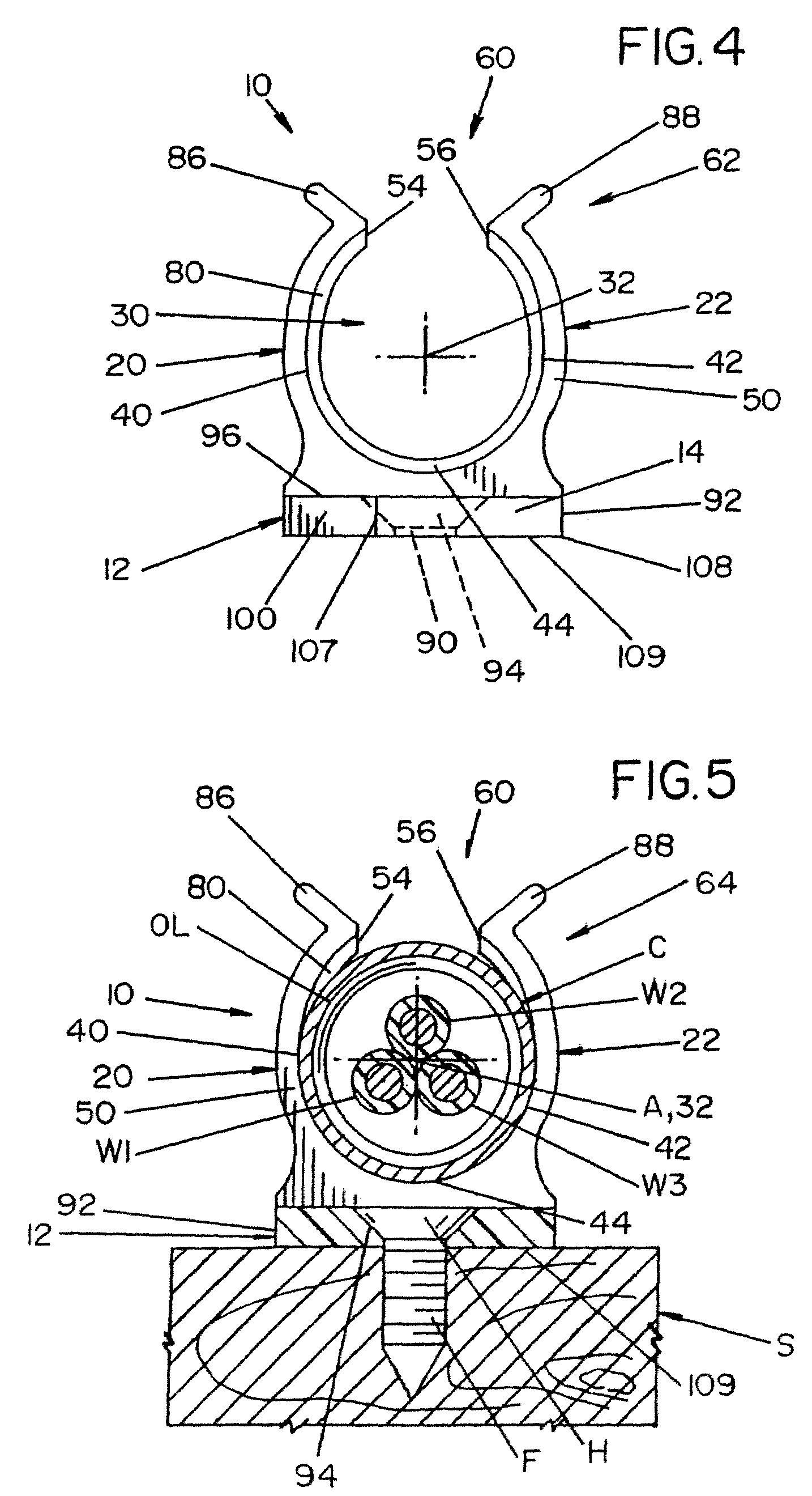
[0027]Referring now in greater detail to the drawings, wherein the showings are for the purpose of illustrating preferred embodiments of the invention only, and not for the purpose of limiting the invention FIGS. 1-7 show a clip 10 having a base portion 12 extending between an end 14 and an end 16 that together define longitudinal direction 18. Clip 10 further includes side walls 20 and 22 that also extend in the longitudinal direction.

[0028]Clip 10 further includes a conduit receiving cavity 30 that is oval or C-shaped which can extend from end 14 to end 16, but can be shorter. Cavity 30 is shaped to receive a section of an armored conduit or MC-cable C to secure conduit C to the clip such that the clip can be used to support the conduit on a structural object such as on a stud S. Cavity 30 extends circumferentially about a cavity axis 32. Cavity 30 is formed at least in part by inner surfaces 40 and 42 of walls 20 and 22, respectively. Inner surface portions 40&42 can be joined to...


PUM


Abstract

A device for securing a conduit to a structural object. The device including a clip having a longitudinally extending clip body with a conduit receiving cavity extending in the longitudinal direction and about a cavity axis with a longitudinally extending conduit receiving slot. The device further including a panel strap securable to the structural object.

Description

[0001]This application is a continuation-in-part of U.S. patent application Ser. No. 11 / 450,119 filed on Jun. 9, 2006 now U.S. Pat. No. 7,456,361 which application claims priority in U.S. provisional application Ser. No. 60 / 688,954, filed Jun. 9, 2005, entitled “CLIP” and U.S. provisional application Ser. No. 60 / 759,715, filed Jan. 18, 2006, all of which are incorporated by reference herein.[0002]The invention of this application relates to the construction industry and the mounting of electrical wiring and other conduits to a structure. More particularly, to a clip system that can be used in connection with flexible armored electrical cable of all varieties (including or MC cable) and other conduits herein after all referred to as conduits.INCORPORATION BY REFERENCE[0003]The present invention relates to electrical wiring other conduits and, more particularly, for a clip system for securing these conduit to a structural component of a facility. Coleman et al U.S. Pat. No. 5,189,719 ...

Claims


Application Information

Patent Timeline
Patent Type & Authority Patents(United States)
IPC IPC(8): F16L3/08
CPCH01R4/48H02G3/32H01R4/646H01R9/037H01R13/65917
Inventor HILL, DOUGLAS C.
Owner HILL DOUGLAS C
Learn More