Antenna mount for selectively adjusting the azimuth, elevation, and skew alignments of an antenna

an antenna and mount technology, applied in the direction of antennas, gearing, antenna details, etc., to achieve the effect of preventing undue twisting of any exterior wiring, convenient and quick security, and efficient and effective search or sweep

Inactive Publication Date: 2015-07-14
WINEGARD
View PDF11 Cites 1 Cited by
  • Summary
  • Abstract
  • Description
  • Claims
  • Application Information

AI Technical Summary

Benefits of technology

[0006]This invention involves an antenna mount for adjusting the azimuth, elevation, and / or skew alignments of an antenna. The mount can be easily and quickly secured to a post or other support by bolts or other arrangements. The mount has a basic gearbox drive including a worm gear and worm wheel. Interchangeable arcuate members can then be inserted in the basic drive design to customize it for azimuth, elevation, and / or skew adjustments in which the desired ranges of movement or rotation may vary. As for example, the arcuate member primarily designed for azimuth adjustments permits the gearbox drive to rotate the attached antenna more than 360 degrees about a vertical axis. This allows for an efficient and effective search or sweep routine to be performed by a controller as well as subsequent fine tuning of the antenna alignment with one or more signals. In doing so, the azimuth drive with this first arcuate member provides two hard stop positions about 400 degrees from each other to provide reference points for the search routine. The hard stops also prevent undue twisting of any exterior wiring that may be attached to the antenna mount.
[0007]Replacing the first arcuate member for the azimuth drive with a modified or second arcuate member can easily and quickly reduce the rotational movement or angle about the vertical axis to as little as 20 degrees or fewer should a special situation call for such a limited azimuth range. However, such a reduced range is usually more suited for elevation adjustments. This is particularly the case in a compact arrangement in which physical restraints may not permit wider movement of the antenna (e.g., dish antenna) without having it strike other parts of the mount or adjacent structures. Should the antenna mount be used for both azimuth and elevation adjustments, two gearbox drives can be used with one having the arcuate azimuth member and the other having the arcuate elevation member. In doing so, the same basic gearbox design is used with simply different arcuate members in it. The drives are then supported to respectively rotate the antenna about vertical and horizontal axes to adjust the azimuth and elevation alignments. Similarly, a third gearbox drive can be provided with a third arcuate member that permits more of a middle range of movement (e.g., 90-180 degrees) that would be more suitable for skew adjustments of the antenna. The various gearbox drives with the interchangeable arcuate members can be used alone or in combinations with one or more of the other drives. In all cases as mentioned above, the same basic gearbox drive can be used thereby decreasing the cost and complexity of manufacture and assembly of the antenna mount and facilitating the installation, operation, and maintenance of it.

Problems solved by technology

This is particularly the case in a compact arrangement in which physical restraints may not permit wider movement of the antenna (e.g., dish antenna) without having it strike other parts of the mount or adjacent structures.

Method used


Image

  • Antenna mount for selectively adjusting the azimuth, elevation, and skew alignments of an antenna
  • Antenna mount for selectively adjusting the azimuth, elevation, and skew alignments of an antenna
  • Antenna mount for selectively adjusting the azimuth, elevation, and skew alignments of an antenna

Examples


Embodiment Construction

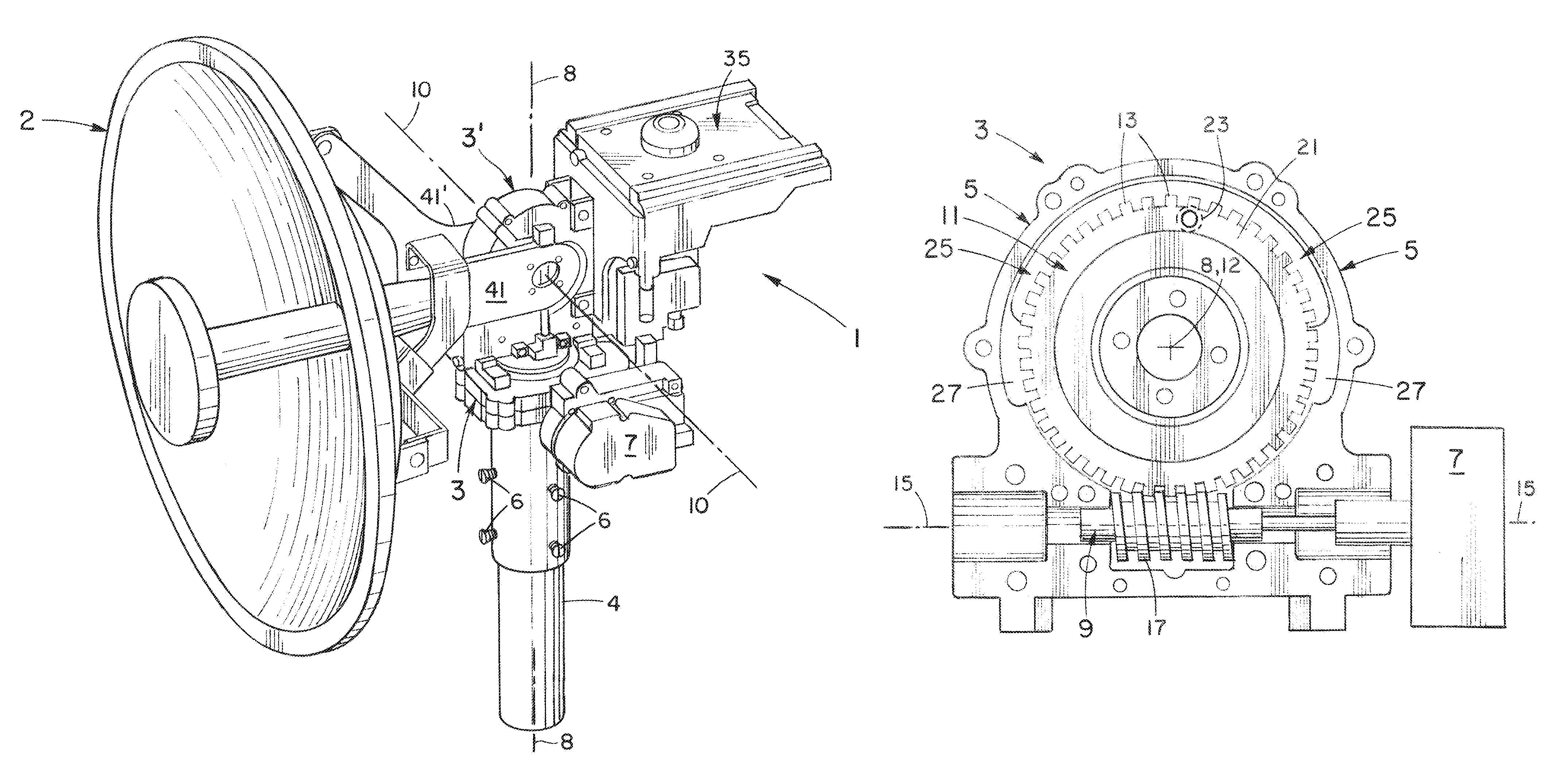
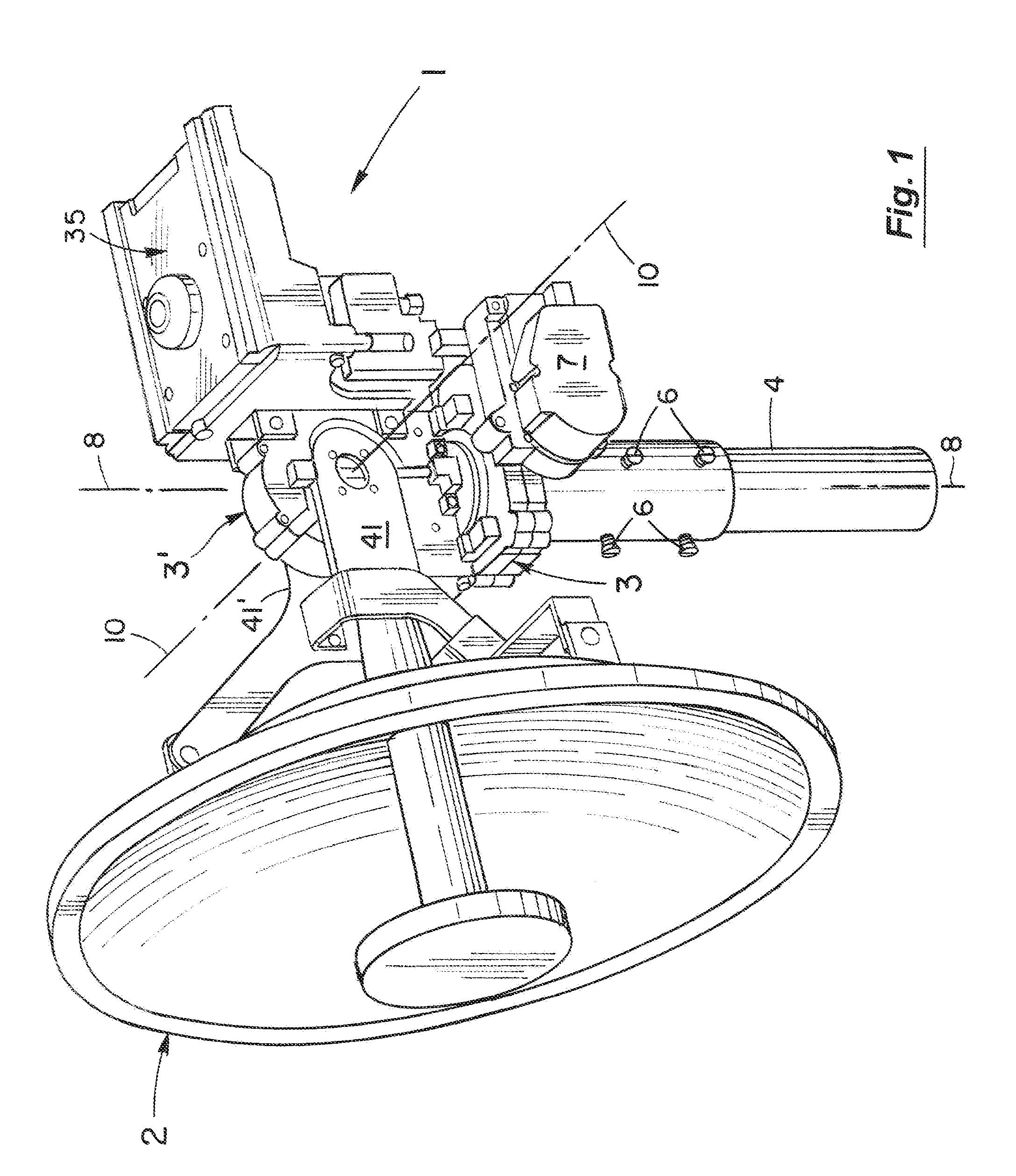
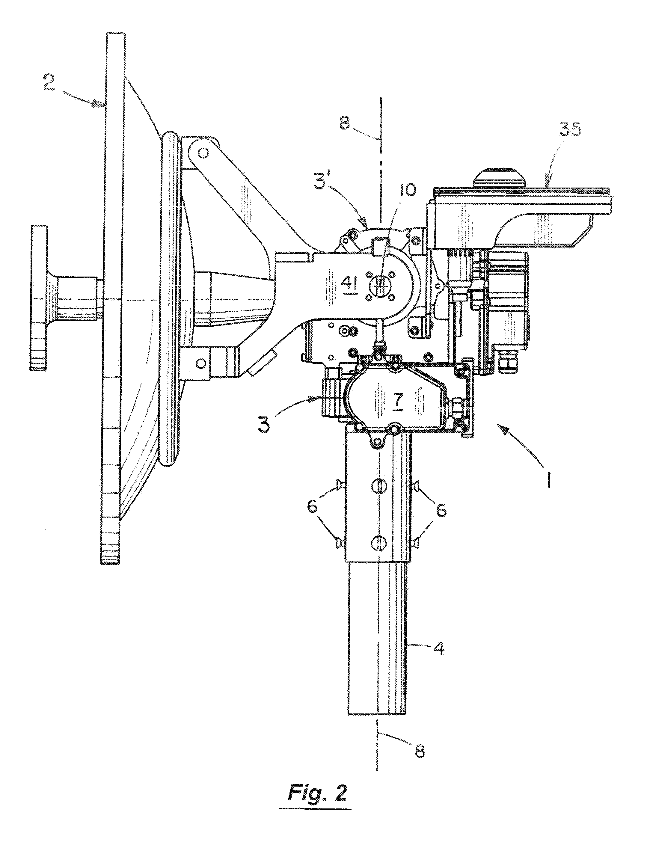
[0023]The antenna mount 1 of the present invention in the embodiment of FIG. 1 is designed to adjust the azimuth and elevation alignments of the antenna 2 (e.g., dish antenna) but as discussed below, its fundamental design can also be used to make skew adjustments to the antenna 2. In the embodiment of FIG. 1, the antenna mount 1 is fixedly securable to a support such as the post 4 by bolts 6 or other arrangements. The antenna mount 1 of FIG. 1 then has a first gearbox drive 3 for adjusting the azimuth alignment of the antenna 2 about the first or vertical axis 8 (see also FIGS. 2-6) and a second gearbox drive 3 for adjusting the elevation alignment of the antenna 2 about the second or horizontal axis 10.

[0024]The internal workings of the gearbox drive 3 for adjusting the azimuth alignment of the antenna 2 of FIG. 1 are shown in the cross-sectional view of FIG. 7. As illustrated in FIG. 7, the gearbox drive 3 has a body 5 with the motor 7 attached to it. The gearbox drive 3 also inc...


PUM


Abstract

An antenna mount for adjusting the azimuth, elevation, and / or skew alignments of an antenna. The mount has a basic gearbox drive including a worm gear and worm wheel with interchangeable arcuate members that can be inserted in the basic drive design to customize it for azimuth, elevation, and / or skew adjustments. The arcuate member for azimuth adjustments permits the gearbox drive to rotate the attached antenna more than 360 degrees and provides two hard stop positions about 400 degrees from each other for reference points for the search routine and to prevent undue twisting of any attached, exterior wiring. Replacing the azimuth arcuate member with a modified or second arcuate member reduces the rotational movement (e.g., to 20 degrees) making the gearbox drive more suitable for elevation adjustments. Similarly, a third gearbox drive can be provided with a third arcuate member with more of a middle range of movement (e.g., 90-180 degrees) suitable for skew adjustments of the antenna.

Description

BACKGROUND OF THE INVENTION[0001]1. Field of the Invention[0002]This invention relates to the field of antenna mounts and more particularly to the field of such mounts for selectively adjusting the azimuth, elevation, and skew alignments of the antenna.[0003]2. Discussion of the Background[0004]Antenna mounts to selectively adjust the azimuth, elevation, and skew alignments of an antenna can often be very complicated, particularly to manufacture and install. Ones that are complicated to manufacture are usually also relatively expensive to make and assemble. Others that are somewhat difficult to install can present multiple problems. To the extent their designs are complicated, the installer may have to follow detailed, written instructions taking undue amounts of time and possibly resulting in time consuming errors that need to be corrected before the installation is complete. Additionally, the installer is typically on a slanted or flat roof or other exterior location exposed to th...

Claims


Application Information

Patent Timeline
Patent Type & Authority Patents(United States)
IPC IPC(8): H01Q1/12F16H25/20H01Q3/08
CPCH01Q1/125F16H25/2015H01Q1/1242H01Q3/08Y10T74/18792
Inventor CONRAD, TIMOTHY JOHNGALLERICK, JOSHUA RICHARD
Owner WINEGARD
Why Eureka
Try Eureka