Drawbar protector

a technology for securing drawers and drawers, applied in the field of securing drawers, can solve the problems of affecting the safety of the securing device itself, and achieve the effect of convenient fabricated and easy and quick securemen

Inactive Publication Date: 2011-06-28
BAUM JAMES T
View PDF12 Cites 2 Cited by
  • Summary
  • Abstract
  • Description
  • Claims
  • Application Information

AI Technical Summary

Benefits of technology

A further object of the invention is to provide a drawbar protector which may be easily fabricated to match the drawbar upon which it is to be attached.
A further object of the invention is to provide a drawbar protector which is easily and quickly secured to the upper rearward end of a tractor drawbar.

Problems solved by technology

Moreover, this Summary is not intended for use as an aid in determining the scope of the claimed subject matter.
In use, wear is experienced on the protector plate rather than on the drawbar itself.

Method used


Image

  • Drawbar protector
  • Drawbar protector
  • Drawbar protector

Examples


Embodiment Construction

Embodiments are described more fully below with reference to the accompanying figures, which form a part hereof and show, by way of illustration, specific exemplary embodiments. These embodiments are disclosed in sufficient detail to enable those skilled in the art to practice the invention. However, embodiments may be implemented in many different forms and should not be construed as being limited to the embodiments set forth herein. The following detailed description is, therefore, not to be taken in a limiting sense in that the scope of the present invention is defined only by the appended claims.

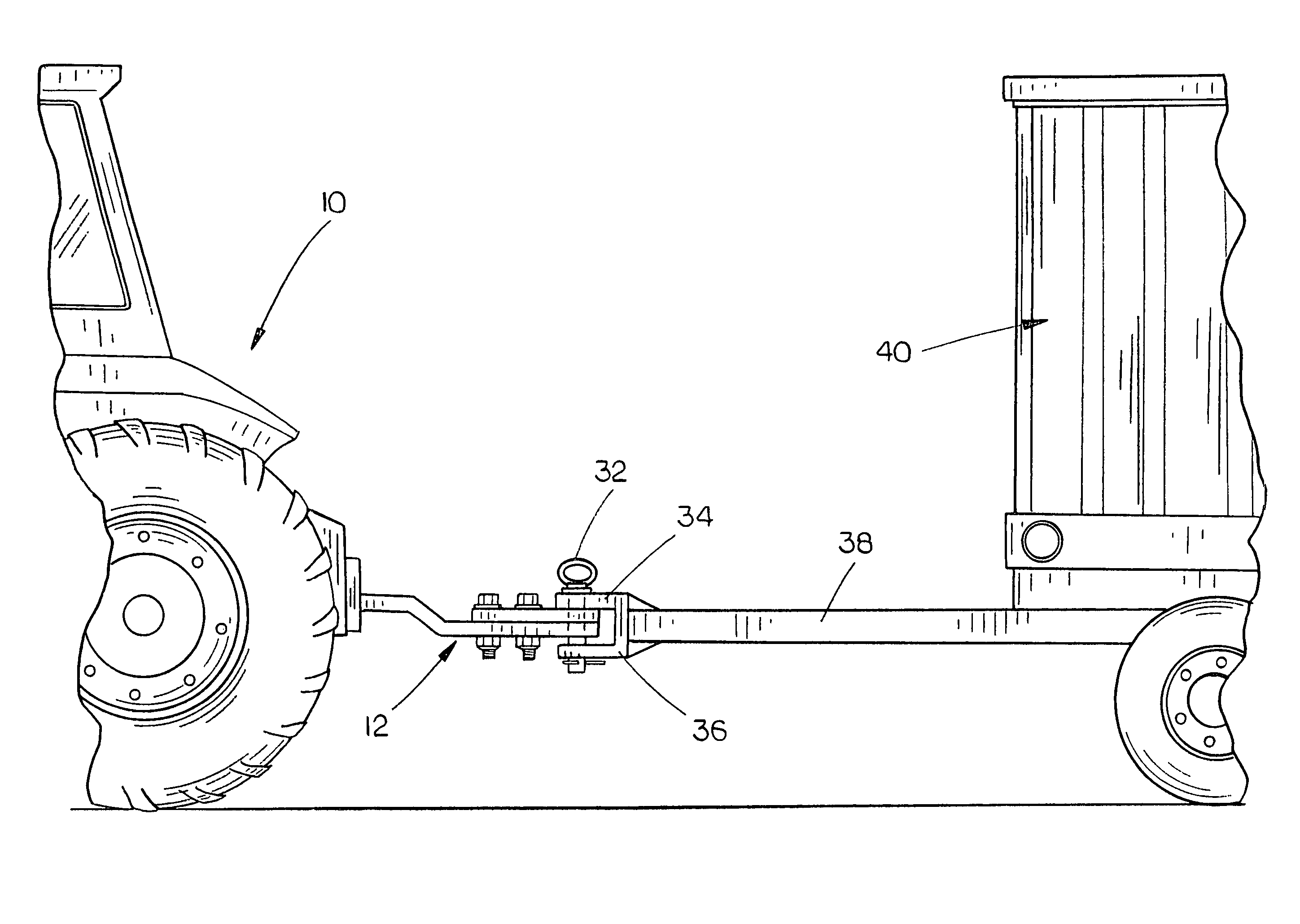
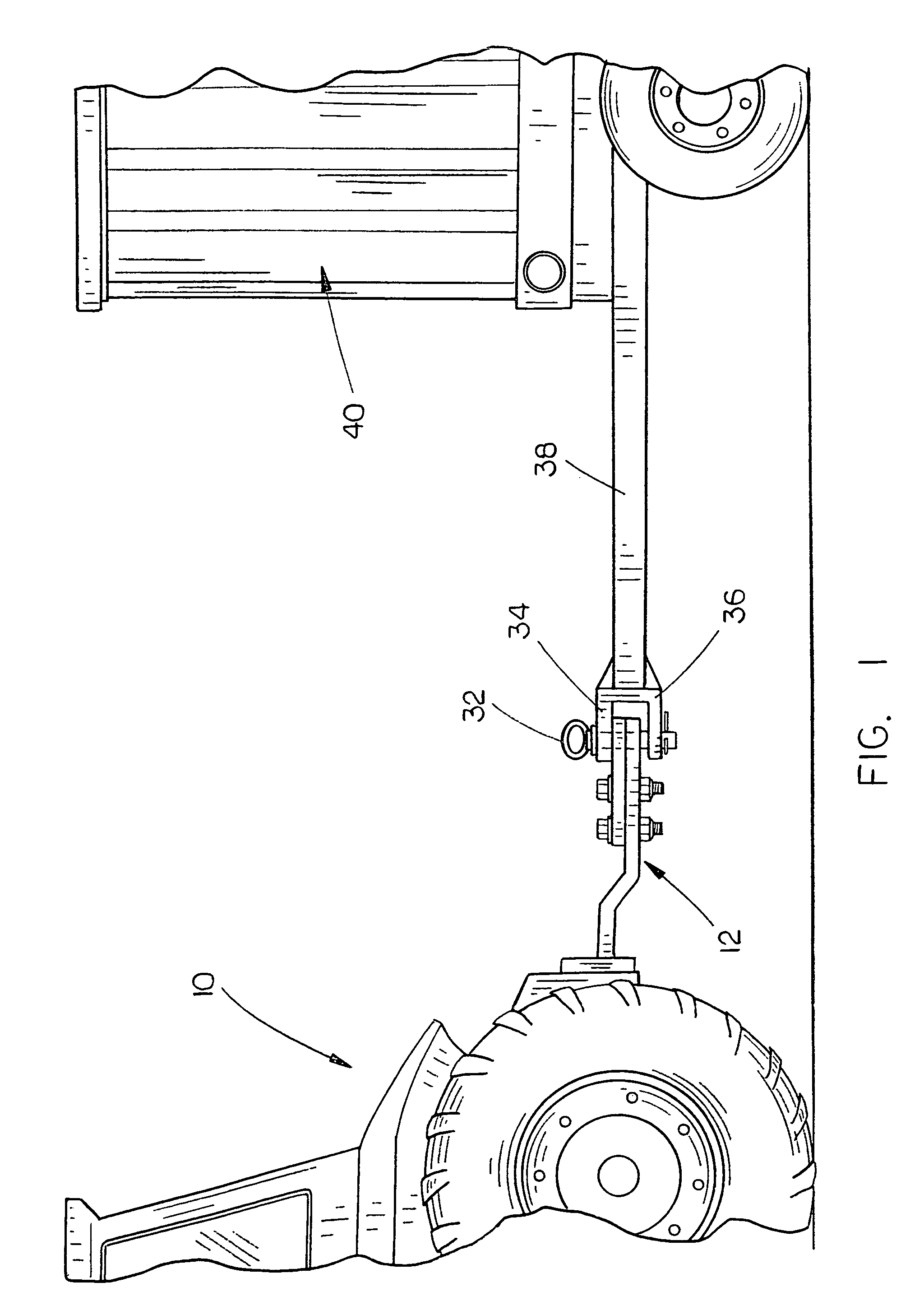
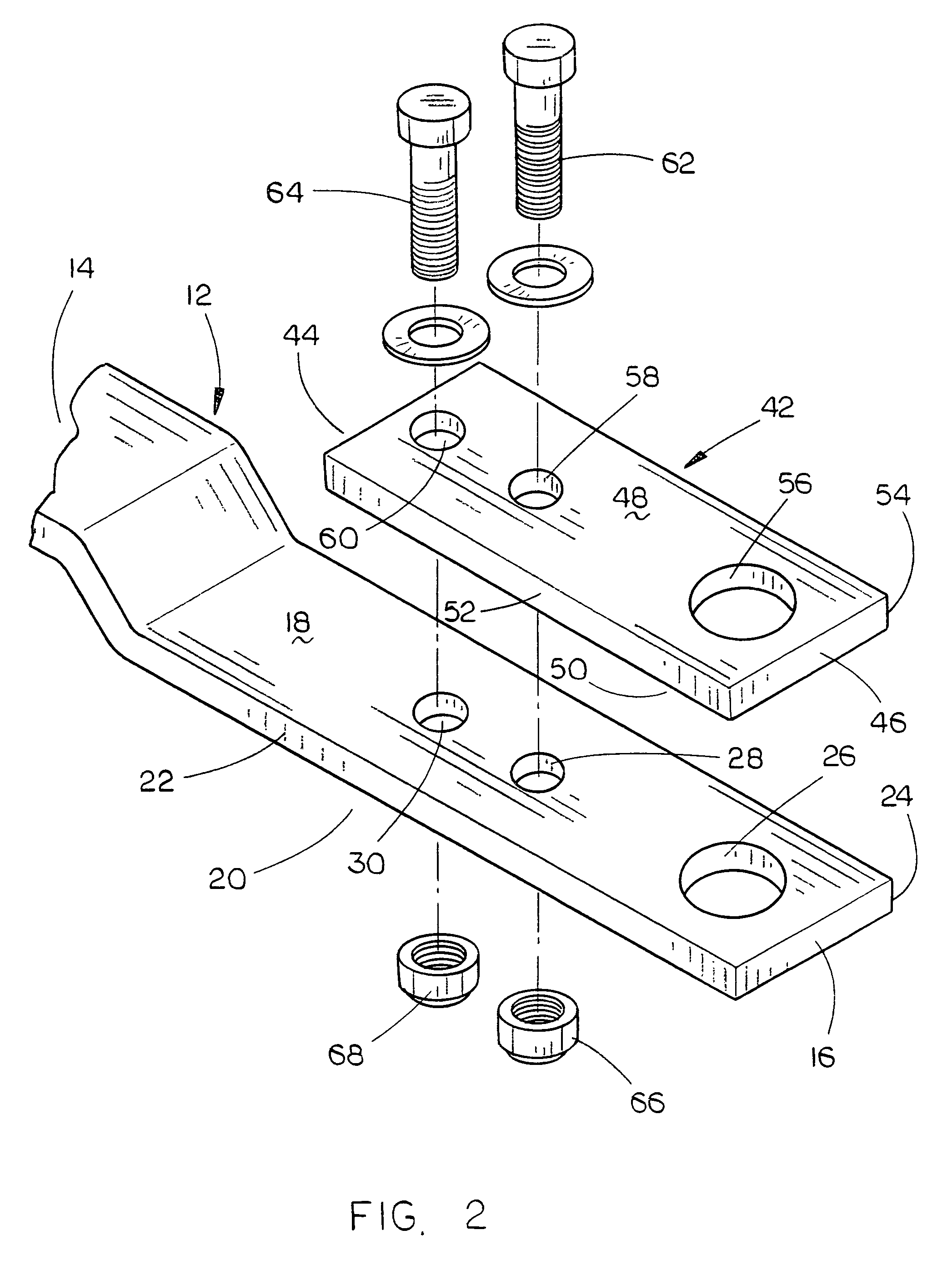
In the drawings, the numeral 10 refers to a conventional tractor having a rearwardly extending drawbar 12 of conventional design. Drawbar 12 will be described as having a forward end 14, a rearward end 16, an upper surface 18, a lower surface 20 and opposite sides 22 and 24. Drawbar 12 includes a hitch pin opening 26 formed therein forwardly of its rearward end 16. Drawbar 12 usually has...


PUM


Abstract

A drawbar protector comprising a generally rectangular plate which is positioned on the upper rearward end of a tractor drawbar so that wear on the drawbar is prevented. If the protector plate becomes excessively worn, it is easily replaced.

Description

BACKGROUND OF THE INVENTION1. Field of the InventionThis invention relates to a drawbar protector and more particularly to a protector which may be secured to and positioned on the upper surface of a tractor drawbar to prevent wearing of the drawbar.2. Description of the Related ArtThe upper surface of a tractor drawbar may become worn especially when the tractor is pulling an implement such as a grain cart or manure spreader which transfers a considerable amount of weight to the drawbar so that the tongue of the implement wears on the upper rearward surface of the drawbar. The worn appearance of a drawbar not only detracts from the aesthetic qualities of the tractor but also indicates that the tractor may have been operated much longer than the hour meter on the tractor indicates. The cost of replacing a worn drawbar is extremely expensive and is time consuming.SUMMARY OF THE INVENTIONThis Summary is provided to introduce a selection of concepts in a simplified form that are furthe...

Claims


Application Information

Patent Timeline
Patent Type & Authority Patents(United States)
IPC IPC(8): B60D1/60
CPCB60D1/60B60D1/02
Inventor BAUM, JAMES T.
Owner BAUM JAMES T
Why Eureka
Try Eureka