

Touch screen with sensory feedback
a technology of sensory feedback and touch screen, which is applied in the direction of pulse technique, switch power arrangement, instruments, etc., can solve the problems of prior art touch dimmers that cannot provide an acceptable amount of sensory feedback to users
- Summary
- Abstract
- Description
- Claims
- Application Information
AI Technical Summary
Benefits of technology
Problems solved by technology
Method used
Image

Examples
second embodiment
[0091]FIG. 15A and FIG. 15B are simplified schematic diagrams of the circuitry for a four-wire touch sensitive device 710 and a controller 714 according to the present invention. The four-wire touch sensitive device 710 has four connections, i.e., electrodes, and provides two outputs: a first output representative of the position of a point actuation along the Y-axis, i.e., the longitudinal axis of the dimmer 100 a shown in FIG. 4B, and a second output representative of the position of the point actuation along the X-axis, i.e., an axis perpendicular to the longitudinal axis. The four-wire touch sensitive device 710 provides the outputs depending on how the DC voltage VCC is connected to the touch sensitive device. A stabilizing circuit 720 is operatively coupled to the first output and a usage detection circuit 722 is operatively coupled to the second output.
[0092]The controller 714 controls three switches 760, 762, 764 to connect the touch sensitive device 710 to the DC voltage VC...
third embodiment
[0093]FIG. 15C is a simplified schematic diagram of the circuitry for the four-wire touch sensitive device 710 and a controller 814 according to the present invention. The controller 814 is operable to read the position of a point actuation on the four-wire touch sensitive device 710 along both the Y-axis and the X-axis. When determining the position along the Y-axis, the controller 814 operates the same as the controller 714 shown in FIGS. 15A and 15B by controlling the switches 760, 762, 764 as described above.
[0094]An additional stabilizing circuit 870 is provided for determining the position of the point actuation along the X-axis. The additional stabilizing circuit 870 comprises a whacking-grade capacitor C872. The controller 814 controls a switch 874 to selectively switch the output of the X-axis between the usage detection circuit 722 and the additional stabilizing circuit 870. The controller 814 controls the switch 874 in a similar fashion to how the controller 214 controls ...
fourth embodiment
[0095]FIGS. 16A and 16B are a perspective view and a front view, respectively, of a touch dimmer 900 according to the present invention. FIG. 17A is a bottom cross-sectional view and FIG. 17B is an enlarged partial bottom cross-sectional view of the dimmer 900. FIG. 18A is a left side cross-sectional view and FIG. 18B is an enlarged partial left side cross-sectional view of the dimmer 900.
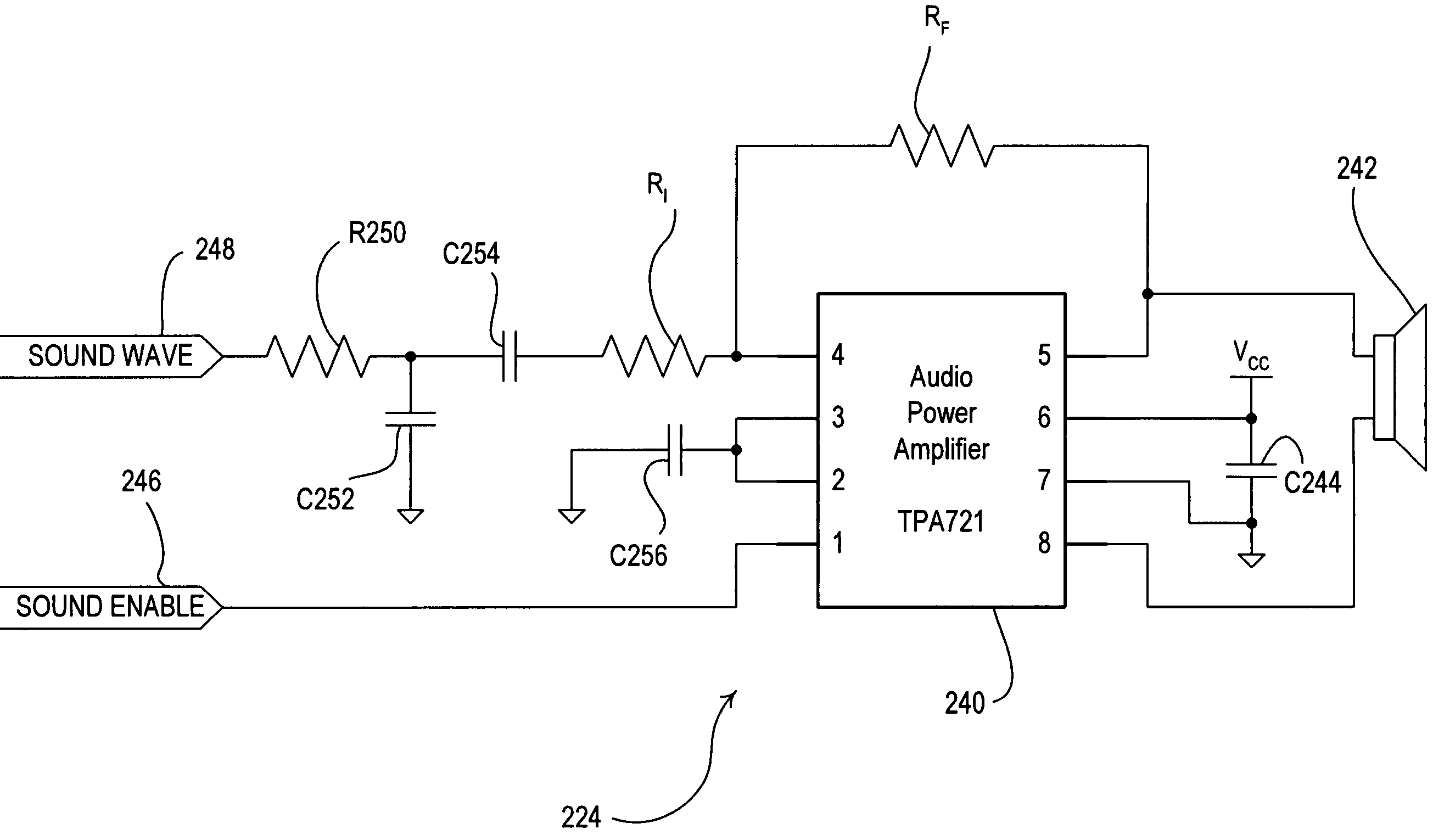
[0096]The touch dimmer 900 includes a thin touch sensitive actuator 910 comprising an actuation member 912 extending through a bezel 914. The dimmer 900 further comprises a faceplate 916, which has a non-standard opening 918 and mounts to an adapter 920. The bezel 914 is housed behind the faceplate 916 and extends through the opening 918. The adapter 920 connects to a yoke 922, which is adapted to mount the dimmer 900 to a standard electrical wallbox. A main printed circuit board (PCB) 924 is mounted inside an enclosure 926 and includes the some of the electrical circuitry of the dimmer 200, e.g., ...
PUM
 Abstract
Description
Claims
Application Information