Curved liquid-crystal display device, and method for the forming and installation of reflective plate/sheet for curved liquid-crystal display device

a liquid crystal display device and liquid crystal display technology, applied in non-linear optics, instruments, optics, etc., can solve the problems of uniformity of light radiated from the light source within the backlight, difference in viewing angle, and increased glare off the screen, so as to suppress brightness non-uniformities

Active Publication Date: 2009-10-27
INFOVISION OPTOELECTRONICS HLDG LTD
View PDF13 Cites 23 Cited by
  • Summary
  • Abstract
  • Description
  • Claims
  • Application Information

AI Technical Summary

Benefits of technology

[0010]Accordingly, it is an object of the present invention to provide a liquid-crystal display device having a concavely curved liquid-crystal panel, in which a uniform brightness of the screen of the liquid-crystal device having a curved screen can be maintained and brightness non-uniformities can be suppressed to a minimum, without making the outer shape of the liquid-crystal display device large.
[0031]With the first aspect of the present invention, the problem of brightness non-uniformities occurring at both the left and right edges of a concavely curved liquid-crystal panel and the problem that spacers installed behind the liquid-crystal panel are visible through the liquid-crystal panel can be remedied without broadening the lateral width of the backlight.
[0032]With the second aspect of the present invention, in addition to the effect of the first aspect of the present invention, it is possible to further remedy brightness non-uniformities and the like with the reflective plate or reflective sheet attached to the inner surface of the spacer support portions of the backlight unit supporting the first spacers and the third spacers.
[0034]With the fourth aspect of the present invention, in addition to the effect of the first to third aspects of the present invention, the fabrication of the reflective plate or reflective sheet becomes easier.
[0039]With the ninth aspect of the present invention, the same effect as in the first aspect can be attained without separately attaching the reflective plate or reflective sheet to spacers.

Problems solved by technology

But a problem with increasingly larger television LCD screens is that the viewing angle difference between the viewing angle when the viewer views the center portion of the screen, and the viewing angle when the viewer views the left and right edges of the screen increases (throughout this specification, the technical term “viewing angle” is defined as the angle between the line of sight of the viewer viewing the screen and the tangent to the intersection between the line of sight and the observed screen surface, and the difference between the center and left / right edge viewing angles is defined as and used to mean the “viewing angle difference”).
Furthermore, another problem with large-scale television LCD screens is that glare off the screens also increases.
However, when a backlight with the same structure as that of a flat liquid-crystal panel is used for a liquid-crystal panel whose screen is concavely curved (in the following also referred to as “concavely curved liquid-crystal panel”), then the uniformity of the light that is radiated from the light source within the backlight is lost due to the influence of spacers or the like that are installed between the concavely curved liquid-crystal panel and the backlight at the periphery of the concavely curved liquid-crystal panel.
As a result, the uniformity of the screen brightness of concavely curved liquid-crystal panels is lower than the uniformity of the screen brightness of conventional flat liquid-crystal display devices.
This countermeasure is undesirable, since it increases the outer form of the liquid-crystal display device.

Method used


Image

  • Curved liquid-crystal display device, and method for the forming and installation of reflective plate/sheet for curved liquid-crystal display device
  • Curved liquid-crystal display device, and method for the forming and installation of reflective plate/sheet for curved liquid-crystal display device
  • Curved liquid-crystal display device, and method for the forming and installation of reflective plate/sheet for curved liquid-crystal display device

Examples


embodiment 1

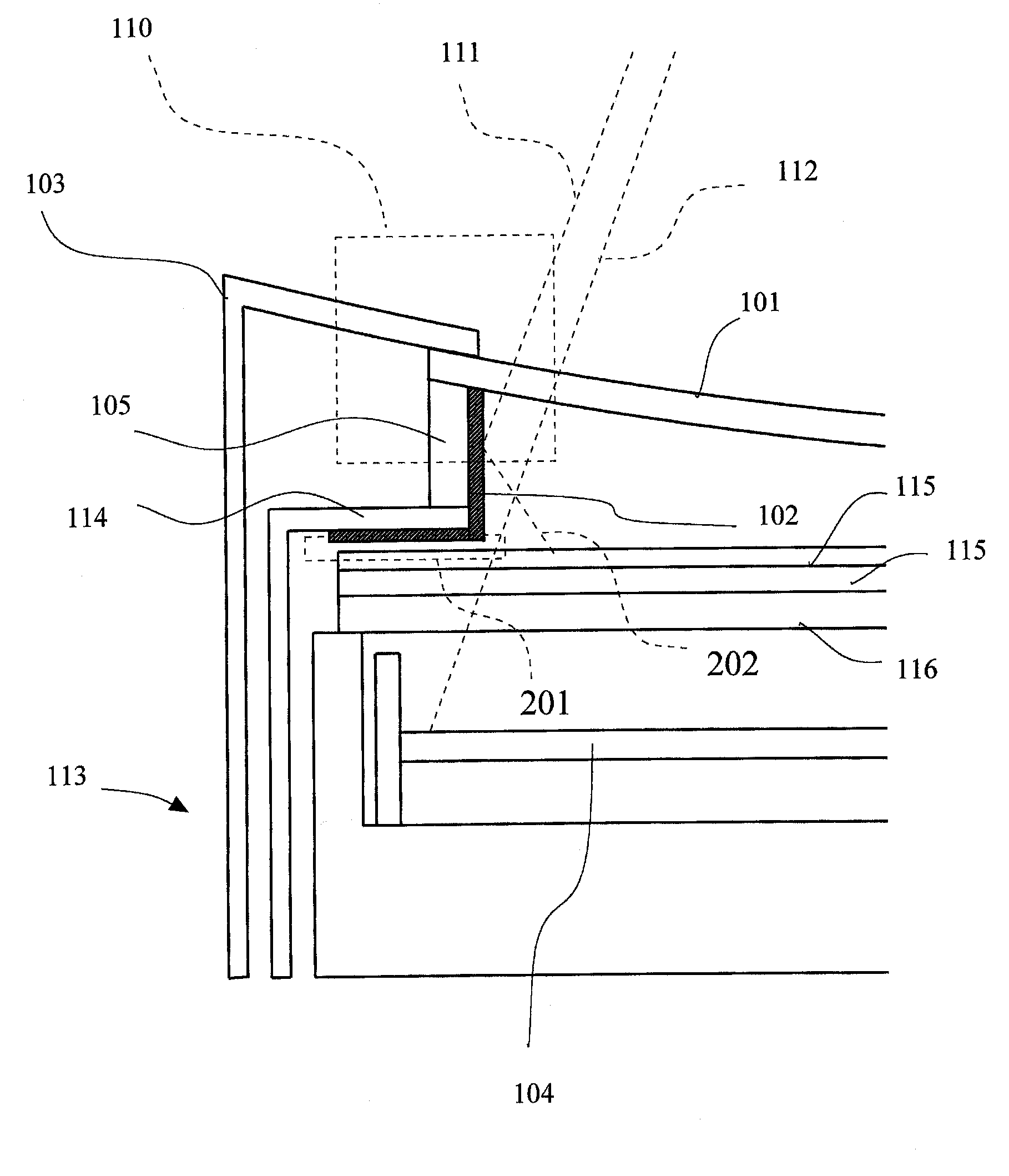
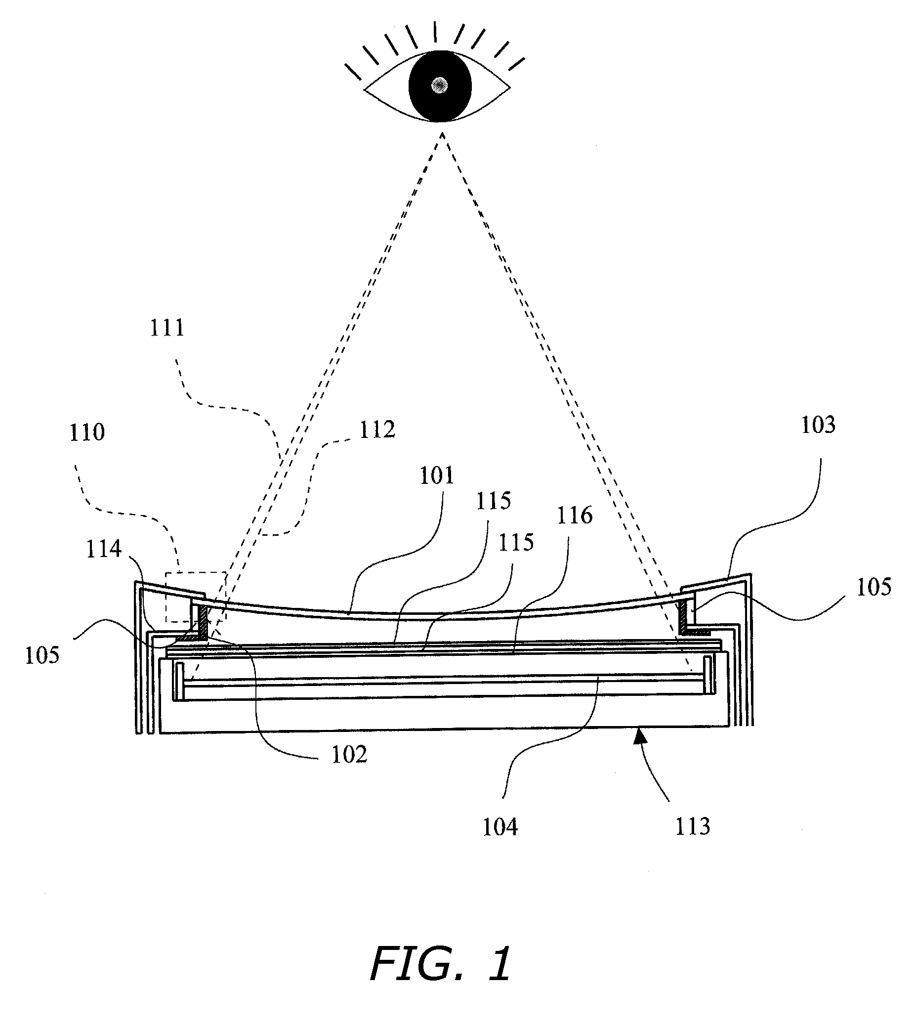
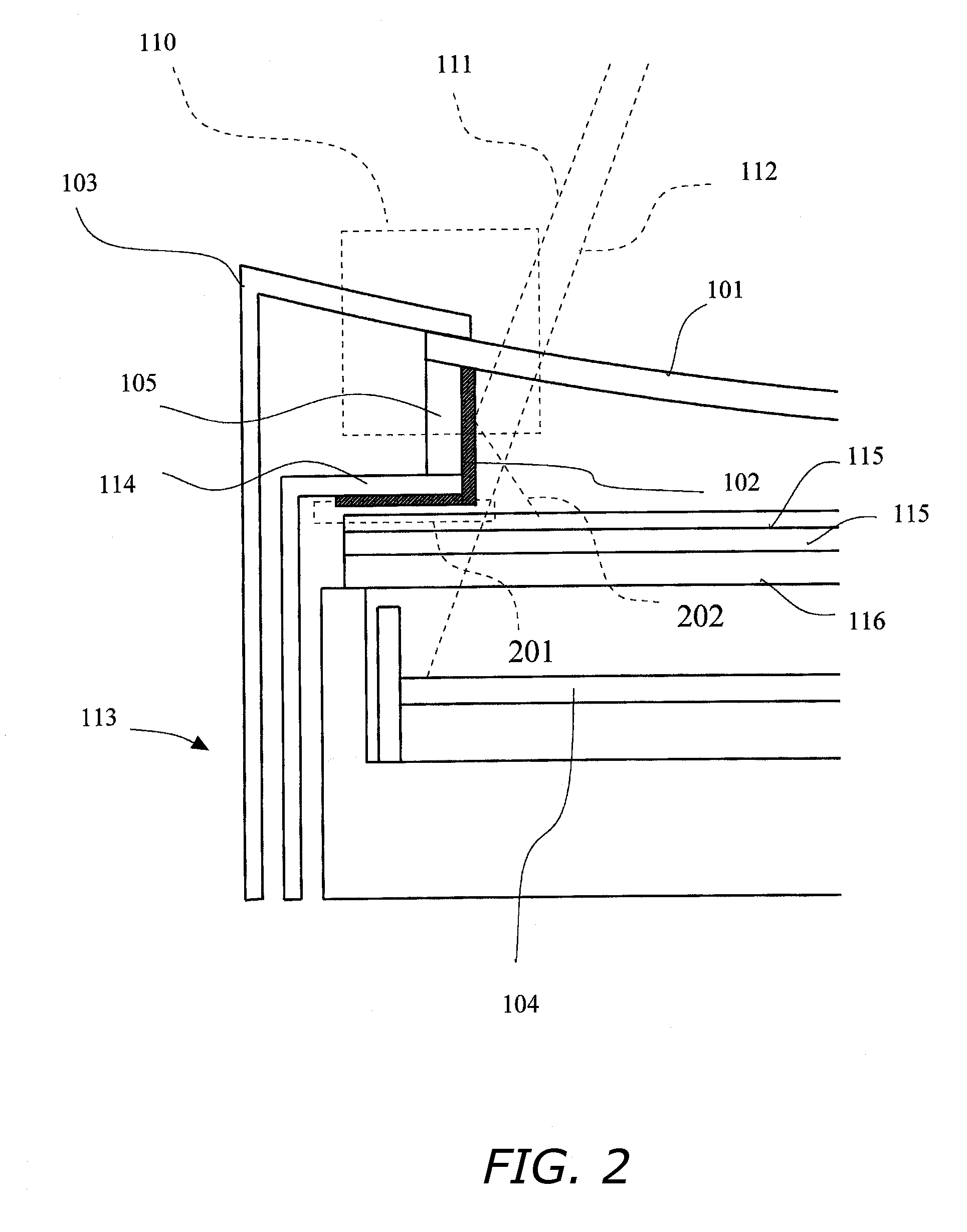
[0064]FIG. 1 is a diagrammatic cross-sectional view illustrating a situation in which reflective plates are installed in a liquid-crystal display device having a concavely curved panel according to Embodiment 1. The liquid-crystal panel 101 is held by the third spacers 105 above the backlight unit 113. Reflective plates 102 are installed on the inner wall of the third spacers 105. The reflective plates are also installed on the spacers in the direction perpendicular to the third spacers 105 shown in FIG. 1. Those perpendicular spacers are the first spacers 301 in FIG. 3. The reflective plates are also installed on the inner walls of the first spacers 301. It should be noted that FIG. 3 is an exploded view of the liquid-crystal panel 101, the third spacers 105, the first spacers 301 and the backlight unit 113, which are the main components of the liquid-crystal display device having a concavely curved panel according to Embodiment 1.

[0065]The general locations where the reflective pl...

embodiment 2

[0075]FIG. 6 is a diagrammatic cross-sectional view illustrating the state in which reflective plates are installed in a liquid-crystal display device having a concavely curved panel according to Embodiment 2. The difference between the installation state of the reflective plates of the liquid-crystal display device having a concavely curved panel according to Embodiment 2 and the installation state of the reflective plates of the liquid-crystal display device having a concavely curved panel according to Embodiment 1 is that the reflective plates of the liquid-crystal display device having a concavely curved panel according to Embodiment 1 are also installed on components other than the spacers, whereas the reflective plates of the liquid-crystal display device having a concavely curved panel according to Embodiment 2 are not installed on any components other than the spacers. With reflective plates installed in this manner, the attained effect does not reach the effect of the liqui...

embodiment 3

[0076]FIG. 7 is a diagrammatic cross-sectional view illustrating a method for forming / installing reflective plates in a liquid-crystal display device having a concavely curved panel according to Embodiment 3. The characteristic feature of the method for forming / installing reflective plates in a liquid-crystal display device having a concavely curved panel according to Embodiment 3 is the aspect that the reflective plates are constituted by a highly reflective material applied to the inner walls of the spacers. If the reflective plates are formed in this manner, the step of installing reflective plates on the spacers or the like becomes unnecessary, extremely thin reflective plates can be formed, and a slight contribution to making the overall liquid-crystal display device smaller can be made.


PUM

PropertyMeasurementUnit
heightaaaaaaaaaa
optical reflectivityaaaaaaaaaa
viewing angleaaaaaaaaaa

Abstract

Liquid-crystal display device with a concavely curved panel in which a reflective plate is installed with which a uniform brightness of the screen of the liquid-crystal device with curved screen can be maintained and brightness non-uniformities can be remedied, without making the outer shape of the liquid-crystal display device large. In a liquid-crystal display device having a structure in which a concavely curved panel is held by spacers having a curved shape that are installed on a backlight unit, a reflective plate or reflective sheet is attached to all those inner walls formed by an inner space enclosed by the concavely curved panel, the spacers and the backlight unit that are formed by components that are installed between the curved panel and the backlight unit and that are formed by components that are not transmissive to light that is emitted from the light source.

Description

BACKGROUND OF THE INVENTION[0001]1. Technical Field[0002]The present invention relates to curved liquid-crystal display devices and methods for forming / installing a reflective plate or reflective sheet used for a curved liquid-crystal display device.[0003]2. Description of the Related Art[0004]In recent years, as liquid-crystal display devices have come to be used as display devices of television receivers, the screens of such liquid-crystal display devices have become increasingly bigger. But a problem with increasingly larger television LCD screens is that the viewing angle difference between the viewing angle when the viewer views the center portion of the screen, and the viewing angle when the viewer views the left and right edges of the screen increases (throughout this specification, the technical term “viewing angle” is defined as the angle between the line of sight of the viewer viewing the screen and the tangent to the intersection between the line of sight and the observed...

Claims


Application Information

Patent Timeline
Patent Type & Authority Patents(United States)
IPC IPC(8): G02F1/1339G02F1/1335
CPCG02F1/1333G02F1/133608G02F1/133605
Inventor NOUCHI, MASANORIMATSUDA, FUMITOSHIHASHIBA, HIROMITSU
Owner INFOVISION OPTOELECTRONICS HLDG LTD
Why Eureka
Try Eureka