Display structure with moving attraction elements

a technology of attraction elements and display structures, applied in display means, advertising, flags/banners, etc., can solve the problems of not allowing the hanging of display structures from the ceilings, limited use of motion, etc., to enhance the attractiveness of display structures, effective draw the attention of show attendees, and light weight

Inactive Publication Date: 2009-11-03
NOWICKI MICHAEL J
View PDF13 Cites 9 Cited by
  • Summary
  • Abstract
  • Description
  • Claims
  • Application Information

AI Technical Summary

Benefits of technology

[0001]This invention relates generally to exhibit and display structures of the type used at trade shows and other similar events and, more particularly, to such a structure that includes moving attraction elements to more effectively draw the attention of show attendees. Exhibit and display structures are important marketing tools used in connection with trade shows, point of purchase locations, billboard and sign advertising, for example. Their primary purpose is to attract potential customers of the products being advertised. Various techniques have been employed to enhance the attractiveness of these displays, including vertical presence, striking color effects, lighting, and motion. The use of motion is presently limited to simple rotation of larger hanging structures or ground-based rotation of an entire structure. However, many exhibit halls do not permit display structures to be hung from the ceilings.
[0002]The current industry trend is toward the use of display structures that employ a thin wall aluminum tubing frame with a tension fabric covering. These structures have the advantage of light weight and compact shipping size, when unassembled. At the same time, they are relatively large when assembled. Representative of the use of tension fabric is U.S. Pat. No. 4,036,244 to Huddle, directed to an enclosure utilizing arch supports covered with a flexible membrane. U.S. Pat. Nos. 5,345,962, 5,441,069, and 5,477,875 to Moss teach fabric structures with a pavilion style of construction. Among the present U.S. manufacturers of tension fabric exhibit and display structures are Moss, Inc., Skyline Displays, Inc., Nimlock, and Tencat Productions, LLC, for example.
[0003]It would be advantageous to provide distributed, synchronized motion to exhibit, display, and other marketing structures that may be easily assembled, disassembled, and transported. In accordance with one embodiment of the present invention, a banging display structure includes segmented upper and lower horizontal circular support tubes and a tension fabric membrane attached in the vertical space between the support tubes. Openings in the fabric membrane permit placement therein of attraction elements supported for rotation from the upper support tube. A drive ring is supported for rotation within the upper support tube. Rotational motion is coupled from a drive motor to the drive ring by way of a miter gear coupling tee assembly and is, in turn, coupled from the drive ring to each of the attraction elements by way of another miter gear coupling tee assembly. In accordance with another embodiment of the present invention, a free-standing tension fabric display structure includes a base and a plurality of segmented upwardly and outwardly extending support tubes and a horizontally-positioned upper circular support tube attached to the top ends thereof. A drive motor is positioned within the base in axial alignment with one of the upwardly and outwardly extending support tubes. A first drive shaft is supported for rotation within that one of the upwardly and outwardly extending support tubes and is coupled to a second drive shaft supported for rotation within the upper circular support tube by way of a miter gear coupling tee assembly. A plurality of attraction elements, depending from the upper circular support tube are driven by way of a miter gear coupling tee assembly connecting each of them to the second drive shaft.

Problems solved by technology

The use of motion is presently limited to simple rotation of larger hanging structures or ground-based rotation of an entire structure.
However, many exhibit halls do not permit display structures to be hung from the ceilings.

Method used


Image

  • Display structure with moving attraction elements
  • Display structure with moving attraction elements
  • Display structure with moving attraction elements

Examples


Embodiment Construction

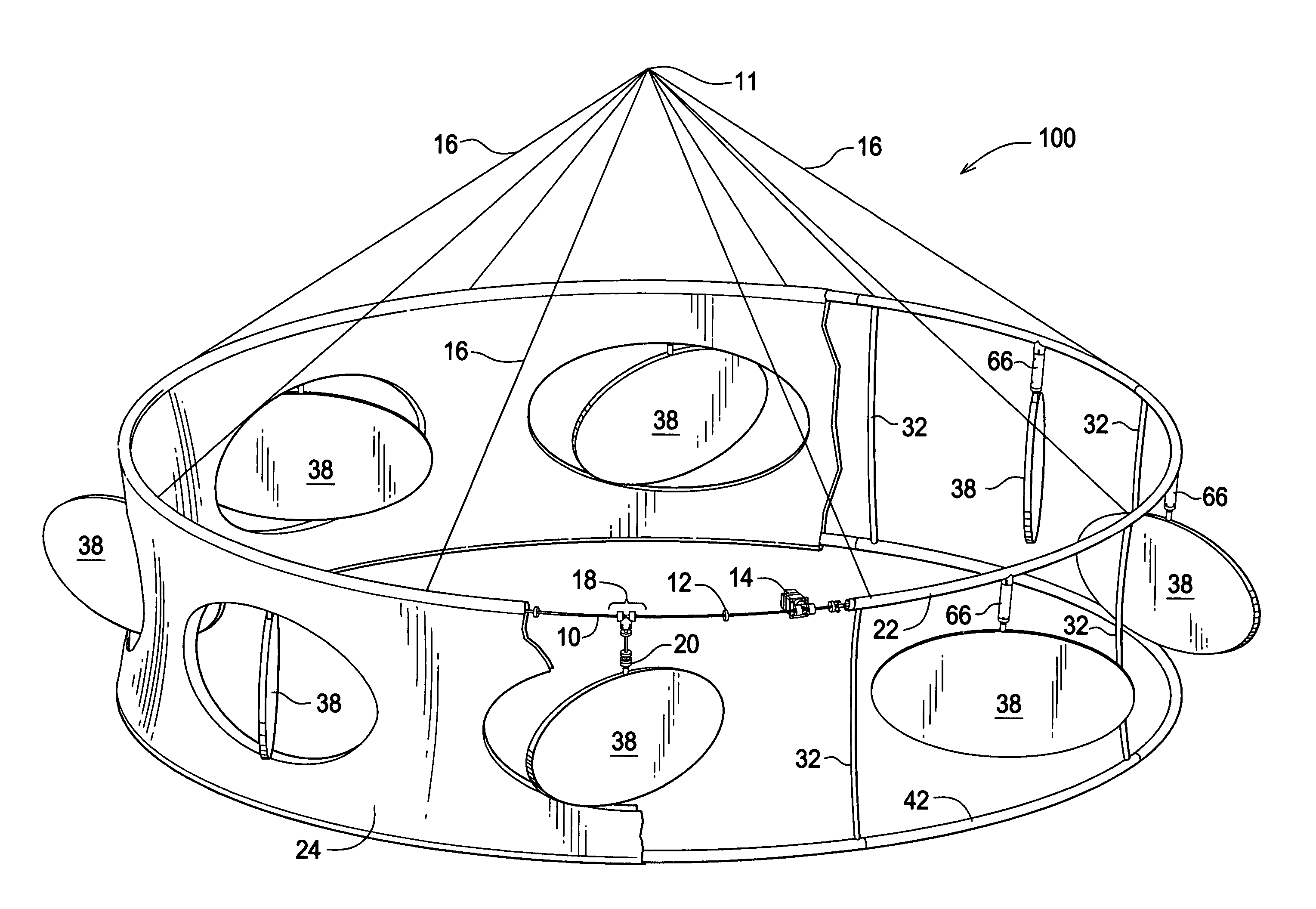
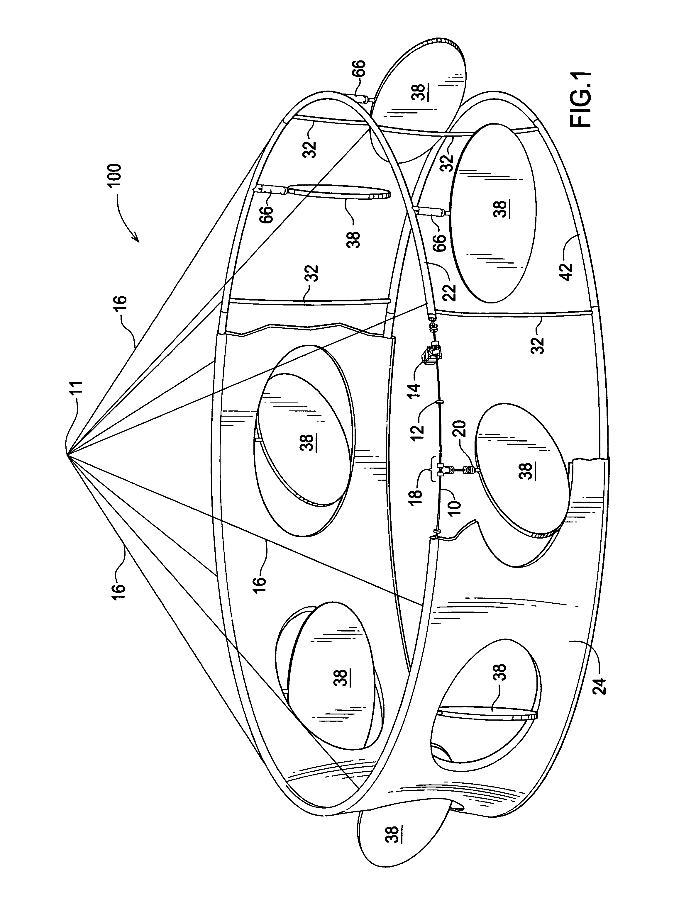
[0016]Referring now to FIG. 1, there is shown a ring banner type of hanging tension fabric display structure 100 adapted to be hung from above at an attachment point 11 by means of a plurality of cables 16. The framework of display structure 100 includes an upper horizontal circular support tube 22, a lower horizontal circular support tube 42, parallel thereto, and a plurality of spaced apart vertical support members 32. Support tubes 22, 42 may be constructed of abutting arcuate sections of any conventional, commercially available material such as aluminum or plastic, for example. A conventional tension fabric membrane 24 generally covers the vertical space between the support tubes 22, 42. A plurality of openings in fabric membrane 24 reveal a like plurality of attraction elements 38 that are suspended for rotation from support tube 22 within the openings. While the attraction elements 38 and their corresponding openings in fabric membrane 24 are shown to be elliptical in shape, t...


PUM


Abstract

A tension fabric display structure incorporates segmented tubular framework permitting easy on-site assembly and disassembly and includes an integral drive motor coupled to a drive shaft that is supported for rotation within a framework tube. Each one of a plurality of attraction elements suspended from the framework tube housing the drive shaft is rotationally driven by a coupling assembly connected to the drive shaft.

Description

BACKGROUND AND SUMMARY OF THE INVENTION[0001]This invention relates generally to exhibit and display structures of the type used at trade shows and other similar events and, more particularly, to such a structure that includes moving attraction elements to more effectively draw the attention of show attendees. Exhibit and display structures are important marketing tools used in connection with trade shows, point of purchase locations, billboard and sign advertising, for example. Their primary purpose is to attract potential customers of the products being advertised. Various techniques have been employed to enhance the attractiveness of these displays, including vertical presence, striking color effects, lighting, and motion. The use of motion is presently limited to simple rotation of larger hanging structures or ground-based rotation of an entire structure. However, many exhibit halls do not permit display structures to be hung from the ceilings.[0002]The current industry trend is...

Claims


Application Information

Patent Timeline
Patent Type & Authority Patents(United States)
IPC IPC(8): G09F19/00
CPCG09F19/02G09F17/00
Inventor NOWICKI, MICHAEL J.
Owner NOWICKI MICHAEL J
Why Eureka
Try Eureka