Marine water drop muffler

Active Publication Date: 2010-10-07
WOODS WOODROW
View PDF18 Cites 10 Cited by
  • Summary
  • Abstract
  • Description
  • Claims
  • Application Information

AI Technical Summary

Benefits of technology

[0013]The present invention overcomes limitations present in the art by providing an improved water drop muffler for use in a marine exhaust system to silence exhaust noise while separating entrained cooling water from exhaust gas using hydro-dynamic centrifugal separation principles enhanced by turbulent flow. A water drop muffler in accordance with the present invention includes a housing having a top and a bottom, and defining an internal volume bounded by a generally vertically disposed cylindrical inner surface formed about a longitudinal axis. The housing further includes a generally tubular exhaust inlet, which is preferably disposed in generally tangential relation with the cylindrical inner housing surface for receiving a mixture of exhaust gas and entrained cooling water. The tubular inlet is in fluid communication with a variable geometry flow channel that efficiently transitions the flow for discharge through a vertically elongate opening disposed along the length of the housing inner surface thereby creating vortex flow within the ho

Problems solved by technology

The tangential inlet and baffle structure disclosed by Ford, however, comprises a fluid handling structure that is inefficient in a fluid dynamic sense, and thus fail to maximize the generation of centrifugal forces thereby resulting

Method used


Image

  • Marine water drop muffler
  • Marine water drop muffler
  • Marine water drop muffler

Examples


Example

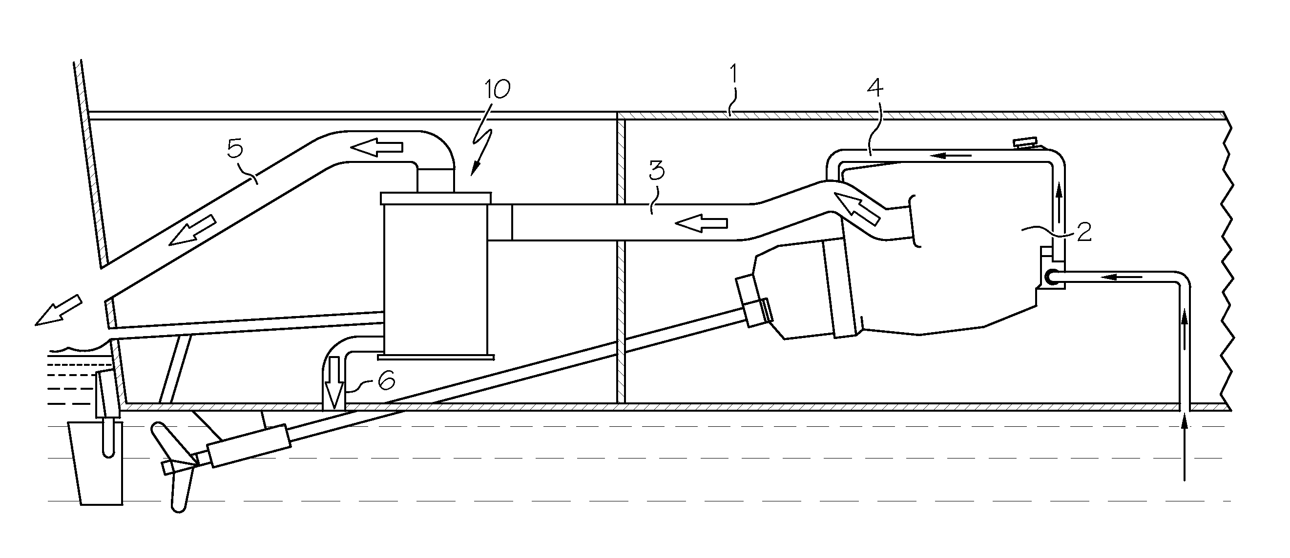
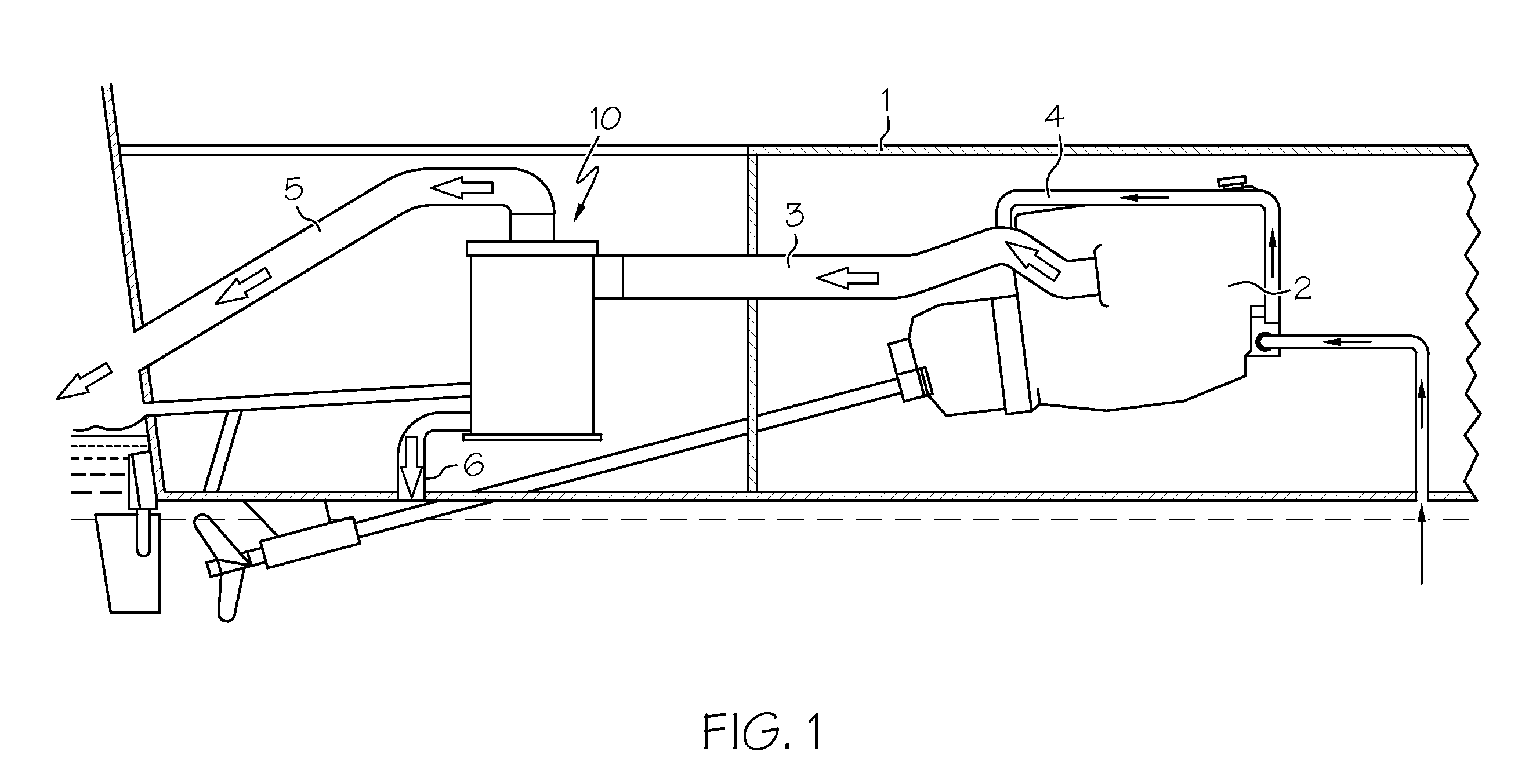
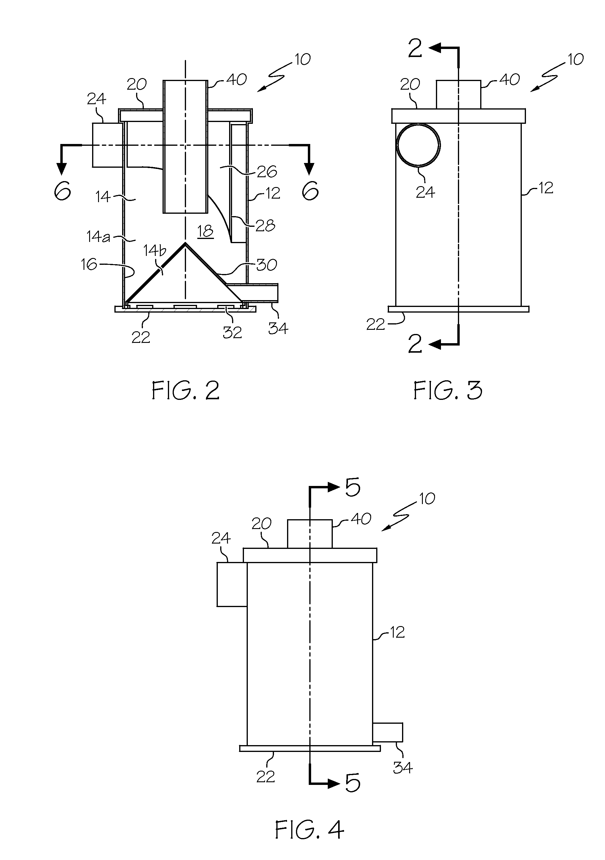
[0026]With reference now to the drawings, FIGS. 1-6 depict a preferred embodiment of a marine water drop muffler, generally referenced as 10, in accordance with the present invention. The present invention overcomes limitations present in the art by providing an improved water drop muffler for use in a marine exhaust system to silence exhaust noise while separating entrained cooling water from “wet” exhaust gas using hydro-dynamic centrifugal separation principles enhanced by boundary layer turbulent flow.

[0027]FIG. 1 is a partial sectional view of a marine vessel, generally referenced as 1, having a water drop muffler, generally referenced as 10, in accordance with the present invention. Marine vessel 1 includes an internal combustion engine 2 having an exhaust conduit 3 connected to a cooling water supply line 4. Exhaust conduit 3 contains a mixture of exhaust gas and cooling water and is in communication with the inlet of water drop muffler 10 of the present invention. Muffler 10...


PUM


Abstract

A water drop muffler for use in a marine exhaust system to silence exhaust noise while separating entrained water from exhaust gas using hydro-dynamic centrifugal separation principles enhanced by turbulent flow. A muffler housing has a top and a bottom, and defines an internal volume bounded by a generally vertically disposed cylindrical inner surface formed about a longitudinal axis. A generally tubular exhaust inlet is disposed in generally tangential relation with the cylindrical inner housing surface for receiving a mixture of exhaust gas and entrained cooling water. A variable geometry flow channel efficiently transitions the flow for discharge through a vertically elongate opening disposed along the length of the housing inner surface thereby creating vortex flow within the housing to maximize the generation of centrifugal forces. The vortex flow formed within the housing causes the relatively heavy water droplets and water vapor (i.e. steam) to be drawn away from the housing axis toward the cylindrical inner surface. In addition, turbulent boundary layer flow along the surfaces of the variable geometry flow forming channel and the other housing surfaces functions to more efficiently draw entrained water droplets and steam into contact with various surfaces within the housing thereby causing water to coalesce along the inner housing surfaces.

Description

CROSS REFERENCE TO RELATED APPLICATIONS[0001]This application claims the benefit of provisional U.S. patent application Ser. No. 61 / 166,882, filed on Apr. 6, 2009.STATEMENT REGARDING FEDERALLY SPONSORED RESEARCH OR DEVELOPMENT[0002]N / ACOPYRIGHT NOTICE[0003]A portion of the disclosure of this patent document contains material that is subject to copyright protection. The copyright owner has no objection to the facsimile reproduction by anyone of the patent document or patent disclosure as it appears in the Patent and Trademark Office patent file or records, but otherwise reserves all copyrights rights whatsoever.BACKGROUND OF THE INVENTION[0004]1. Field of the Invention[0005]The present invention relates generally to exhaust systems and mufflers for use with internal combustion marine engines, and more particularly to a water drop marine engine muffler that uses centrifugal force and turbulence to separate entrained water from marine exhaust gas thereby combining improved water separa...

Claims


Application Information

Patent Timeline
IPC IPC(8): F01N1/08F01N13/00
CPCF01N1/088F01N13/004F01N3/04
Inventor WOODS, WOODROW
Owner WOODS WOODROW
Why Eureka
Try Eureka