Device for the treatment of a liquid or gaseous medium by means of UV radiation

a technology of ultraviolet radiation and gaseous medium, which is applied in the direction of ohmic-resistance heating devices, water/sludge/sewage treatment, lavatory sanitory, etc., can solve the problems of limiting the operating pressure of the device significantly, requiring a very high energy of the uv radiation source, and the known device has a small space. , the effect of low design

Active Publication Date: 2012-04-10
HARTIG HEINZ
View PDF17 Cites 5 Cited by
  • Summary
  • Abstract
  • Description
  • Claims
  • Application Information

AI Technical Summary

Benefits of technology

[0010]In comparison to conventional devices of the same genre, the device according to the invention can be designed relatively small, compact and with a low design, and requires little space. Yet it is very robust. The compact design also allows operation at a higher pressure than is possible with the state-of-the-art device; this increases the throughput of the medium or allows for the same medium throughput for smaller than the larger known devices. While known devices operate, for example, at about 1.5 bar, the device subject to the invention can easily operate at 4.5 bar, for example. Due to the layered, or multi-layered arrangement of the treatment chambers, the time of exposure of the medium to be treated, and of the contamination contained in it, can be increased significantly in the area of exposure in spite of the small design. Due to the design subject to the invention, the radiation area of the UV radiation source can be utilized optimally and the exposure time can be maximized in a small space because the medium to be treated is guided through the area of exposure of the UV radiation source several times during its travel through the device. Furthermore, because of its special design, the device subject to the invention offers addition possibilities for prolonging the time of exposure as will be described in greater detail below.
[0011]Because of the increased exposure time of the medium to be treated in the irradiation area of the UV radiation source, the device subject to the invention has a significantly improved degree of sterilization or oxidation compared to the known solutions. Microorganisms contained in the medium can be deactivated reliably. And potential harmful organic substances can be fully oxidized or broken down to non-toxic compositions. Furthermore, a particular advantage of the device according to the invention is that it can be used to carry out a combined UV sterilization and UV oxidation process (following called combined UV process for short) within one single unit. This possibility is primarily the result of the special layered arrangement of the successive treatment chambers transmissive to UV radiation combined with the increased exposure time of the medium and the duration that the UV radiation can act on the medium and its contamination. With a suitable selection of the UV radiation source's spectral range, the combined UV process both sterilizes the medium by damaging the DNA of the contained microorganisms and destroys and fully breaks down the molecular composition of the remaining deactivated microorganisms or viruses through photochemical oxidation (e.g., in the course of a wet oxidation). The result is a very high degree of purification.
[0012]Potential effects from low tolerances against certain proteins or chemical compositions of deactivated but physically still present microorganisms or microorganism residue in the medium that may occur with conventional UV sterilization are avoided. Depending on the type of radiation source used, or the arrangement of the individual UV radiation sources, with this achievable combined UV process, the UV sterilization and the UV oxidation can effectively transition seamlessly into each other or can be carried out sequentially in succeeding treatment chambers.
[0014]Although in principle it is possible to use separate oxidizing agents during the UV oxidation with the combined UV process that can be realized with the device according to the invention, as a rule this is not necessary because of the achievable high efficiency. Thus, the risks associated with the use of such chemicals can be avoided. Due to the optimum utilization of the UV radiation, the device subject to the invention requires only one UV radiation source with a comparatively low energy. Thus, the device according to the invention operates with high efficiency, low operating costs, low maintenance expenses and, therefore, great cost-effectiveness.

Problems solved by technology

The high absorption of the DNA in this UV radiation range triggers a photochemical reaction, which causes a disruption of the genetic information for cell multiplication and metabolism in the irradiated microorganisms.
This overall size not only requires substantial space, it also limits the operating pressure of the device significantly due to manufacturing difficulties.
Furthermore, the known device requires very high energy of the UV radiation source.
Additionally, it has become apparent that often a portion of the microorganisms did not become fully deactivated with conventional devices used for UV sterilization.
This may be harmful to persons who have a low tolerance against certain proteins or chemical compositions.
In the case of incomplete UV oxidation, harmful organic substances may remain in the medium, which is also not desirable.

Method used


Image

  • Device for the treatment of a liquid or gaseous medium by means of UV radiation
  • Device for the treatment of a liquid or gaseous medium by means of UV radiation
  • Device for the treatment of a liquid or gaseous medium by means of UV radiation

Examples


first embodiment

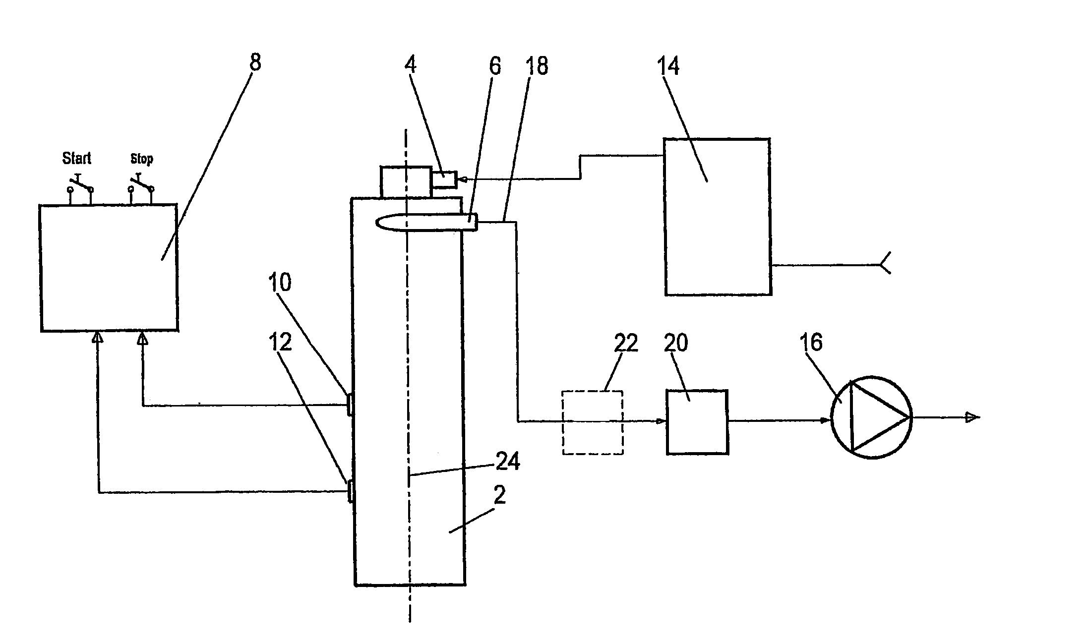
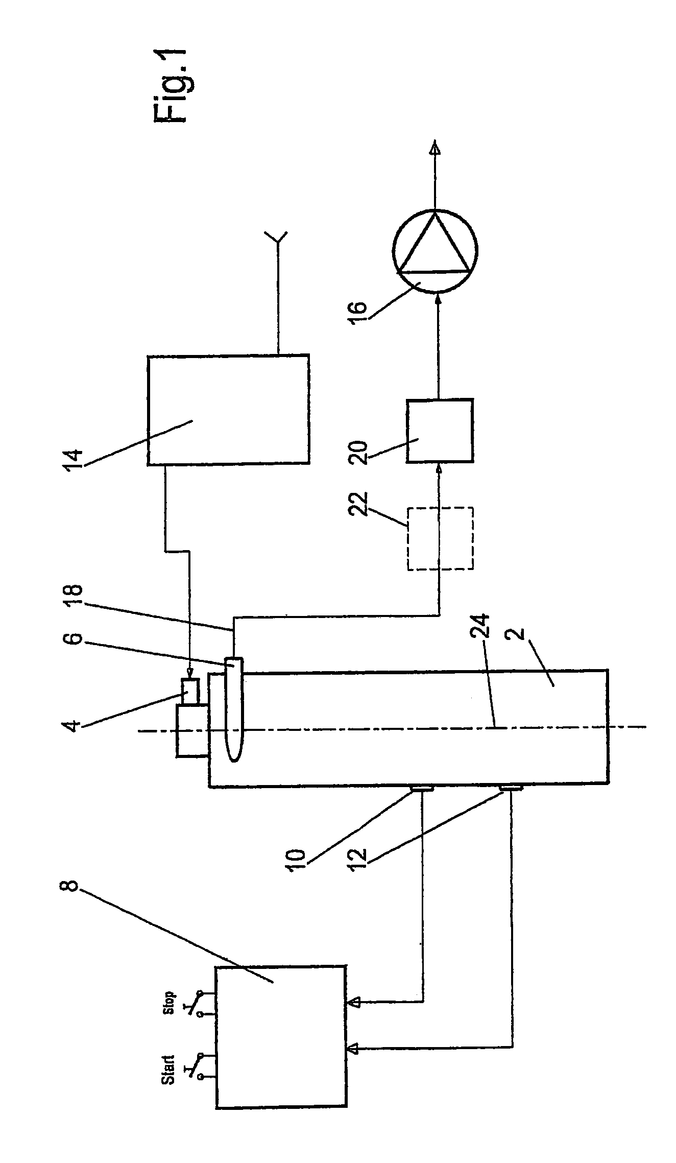
[0034]FIG. 1 shows a schematic block diagram of a device according to the invention for treating a liquid or gaseous medium using UV radiation according to a As essential components, the device comprises a reactor 2 with a supply channel 4 for the liquid or gaseous medium to be treated and an outlet channel 6 for the treated medium. In the exemplary embodiment at hand, water that is contaminated with microorganisms or viruses as well as harmful organic substances is used as the medium to be treated.

[0035]The reactor 2 is coupled with a control device 8, which in this case features two safety and control sensors 10, 12 (here: one optical sensor and one temperature sensor). In addition, the device exhibits a pre-filter device 14 upstream of the supply channel 4 as well as a pump 16, which is located in a line 18 that is connected to the outlet channel 6. A solenoid valve 20 is provided between the outlet channel 6 and the pump 16. A filter device 22 (e.g., an activated carbon filter)...

second embodiment

[0059]FIG. 7 shows a schematic view of a longitudinal section through a device subject to the invention according to a With this variation, the respective layered treatment chambers K1-K4 are arranged helically around the UV radiation source 24.

[0060]FIG. 8 shows a schematic view of a cross-section through a device subject to the invention according to a third embodiment. The functional principle of this variation corresponds essentially to that of the first embodiment, however the layered treatment chambers K1-K4 are grouped in a plate- or box-like arrangement and the UV radiation source 24 is placed on the side of this arrangement. Each treatment chamber K1-K4 exhibits a meander-like flow path (not shown) for the medium to be treated. For a greater yield of the UV light, the device is equipped with a parabolic reflection device 32, which focuses the UV light emitted by the UV radiation source 24 onto the layered treatment chambers K1-K4.

fourth embodiment

[0061]FIG. 9 shows a schematic view of a cross-section through a device subject to the invention according to a The embodiment according to FIG. 9 is in principle similar to that according to FIG. 8, however, two individual UV radiation sources 24a, 24b are provided that irradiate the layered treatment chambers K1-K4 from two different sides. The first individual UV radiation source 24a emits UV light at a spectrum below 200 nm and the second 24b at a spectrum above 200 nm. If a group of treatment chambers is assigned to each of these individual UV radiation sources 24a, 24b, and if, for example, a filter or a separating UV reflection device 34 is located between them, then the UV sterilization and the UV oxidation can occur separated by time and location within the device, for example, the UV sterilization first followed by the UV oxidation. The first or second material for the respective transparent, UV-transmissive separating layers can act as the filters.


PUM

PropertyMeasurementUnit
wavelengthaaaaaaaaaa
wavelengthsaaaaaaaaaa

Abstract

A device for the treatment of a liquid or gaseous medium, in particular water or air, using UV radiation, comprises a UV radiation source (24), with an axial longitudinal direction and an essentially perpendicular, in particular radial direction of irradiation (R), with several layers of transmissive treatment chambers (K1-K4), serially arranged one on the other in the radiation direction (R), separated from the UV radiation source (24) and from each other by a transparent, UV-transmissive separating layer (T1-T4) which is UV transparent. The chambers, beginning with a first treatment chamber (K1), adjacent to the UV radiation source, form a flow channel for the medium running in the longitudinal direction of the UV radiation source (24), the flow channel emptying (26) into the subsequent treatment chamber (K2, K3, K4) that is at a greater distance from the UV radiation source (24) in the direction of irradiation (R).

Description

TECHNICAL FIELD[0001]The present invention relates to a device for the treatment of a liquid or gaseous medium using ultraviolet radiation (UV radiation). In addition, the invention relates to a particularly suitable application of this device.STATE OF THE ART[0002]The term UV radiation is given to electromagnetic radiation that is located between the visible border of short-wave light and x-radiation, and that covers a wavelength range of between about 100 nm to 400 nm. A distinction is made between the following zones: UVA radiation: 400-315 nm; UVB radiation 315-280 nm; UVC radiation about 280-200 nm; VUV radiation: about <180 nm. Devices for treating liquid or gaseous mediums using UV radiation are used, for example, for UV sterilization or UV oxidation.[0003]As a rule, UVC radiation is used for UV sterilization, which effectively destroys microorganisms such as bacteria, yeast and fungi by damaging their DNA (deoxyribonucleic acid). A UV radiation wavelength in a range of ab...

Claims


Application Information

Patent Timeline
Patent Type & Authority Patents(United States)
IPC IPC(8): C02F1/32A61L2/10A61L9/20B01D53/00B01J19/12C02F1/00C02F1/28H05B3/00
CPCC02F1/325C02F2201/3223C02F2201/3228C02F2201/328C02F2301/024C02F2301/026A61L9/20B01D53/007B01D2257/91B01D2259/804B01J19/123B01J2219/0869B01J2219/0875B01J2219/0877C02F1/001C02F1/283C02F2201/326H05B3/0052H05B2203/021H05B2203/022Y02W10/37
Inventor ARAIZA, RAFAELHARTIG, HEINZ
Owner HARTIG HEINZ
Why Eureka
Try Eureka