The comminution of waste & other materials

a technology of waste and other materials, applied in the field of solid waste comminution and screening, can solve the problems of reducing the operating efficiency of the machine, clogging the screening aperture, and reducing the service life of the machine, and achieves the effect of strong shearing effect, high instantaneous load and increased shearing

Inactive Publication Date: 2012-04-12
PROGRESSIVE IP
View PDF4 Cites 10 Cited by
  • Summary
  • Abstract
  • Description
  • Claims
  • Application Information

AI Technical Summary

Benefits of technology

[0074]In addition, on preferred embodiments, the projecting macerating features on the outer and inner drums come into close proximity to each other when measured along a direction (such as in FIG. 1) parallel to the longitudinal axes of the drums (the close proximity of alternating teeth (i.e. alternating between adjacent drums) is best seen in FIGS. 6 and 7). Hence, materials being drawn between the drums in an ever tightening distance, cannot easily avoid the teeth (or other macerating feature) by diverting to either side of the tooth or feature it is encountering. Instead, because teeth are side by side next to each other (the actual arrangement is more complex than this, which will be discussed below), the material is ultimately forced between a tooth and the surface of the other drum rather than merely passing either side of a tooth or projecting macerating feature. By positioning teeth (i.e. projecting macerating feature) side by side adjacently in close proximity (albeit in an alternating arrangement on the two drums) we avoid a combing effect by the teeth on the waste material, and instead introduce a strong shearing effect—particularly if the relative surface speeds of the drums differ and we have the additional action of one set of teeth (i.e. projecting macerating feature) attempting to draw waste material through a tight gap between two adjacent teeth on the opposite drum—this will become more readily apparent in the accompanying illustrations.
[0075]Hence, ideally when travelling along the direction of the longitudinal axes of the drums (assuming the drums are parallel in this example), we shall see the teeth of one drum alternating in position with the teeth of the other drum as we travel along the axis—however in the illustrated preferred arrangement the teeth of each drum are also arranged helically, rather than just linearly (as per a simpler embodiment). This potential intermeshing between alternating teeth creates a strong shearing effect as previously mentioned, which tends to tear apart and macerate most waste material—including fibrous material, and film material (e.g. many plastics). This shearing effect can be increased when there is a difference in the tangential velocities of the inner and outer drums.
[0076]While each projecting macerating features could extend about the entire circumference of each drum with which it is associated, it is instead preferred that individual projecting macerating features which extend only a portion of the circumference of a drum are used. Hence in preferred embodiment, each projecting macerating feature is a tooth element. This arrangement is considered to assist in grabbing and drawing irregularly shaped articles between the drums for maceration.
[0077]Further, aligning the projecting macerating features in a linear row so that all of the teeth on both the inner and outer comminution drums intermesh (when viewed along a direction parallel to a said drum longitudinal axis) simultaneously can place a high instantaneous load on the drums, their teeth, and drive motors. So as to avoid and even out such loadings, preferred embodiments progressively stagger the projecting macerating features about the circumference of the drum as one travels in a direction parallel to the longitudinal axis of the drum. Where the projecting macerating features are teeth, the resulting distribution patterns of teeth about the drum surface appears helical (see figures). A potentially realisable advantage here is that rather than instantaneously loading all teeth simultaneously as the drum(s) rotate, load is progressively introduced to new teeth as one travels in the aforesaid longitudinal direction. Hence any load from intermeshing teeth is small and localised (and continually moving), rather than being on the entire drum simultaneously. Also the loading on motors is substantially continuous—rather than periodically alternating between low and high loads. This allows for the use of less powerful drive motors, and typically greater efficiency.
[0078]By providing multiple helical patterns of teeth about a drum's exposed surface (i.e. inner and outer drums) there can be several localised load points simultaneously along the drum. By arranging the helical pattern(s) of projecting macerating features appropriately, these localised load points can be relatively evenly distributed along the length of a drum at one time. This arrangement places much less stress on the drums and apparatus, while the progressive tooth (i.e. projecting macerating feature) engagement action between drums appears to be quite effective in drawing irregularly sized materials of differing compositions between the drums for maceration.

Problems solved by technology

However, a limitation of the invention was that it worked best with material which did not have a high moisture content and which responding well to a chipping action—e.g. woody and brittle materials.
In practice, stringy fibrous materials such as flax could eventually clog the machine, its screening apertures, and / or reduce its operating efficiency.
Green waste and municipal waste represent a significant problem world wide.
There may also be a significant proportion of stringy and fibrous material.
This type of waste can be bulky due to large air voids and pockets arising from the typically varied composition of this waste, and comprises materials of substantially different size—from branches and limbs, through to small individual pieces such as lawn clippings.
These issues represent a problem for composting—for efficient composting ideally all the material is of a similar size (and ideally blended), and absent of large air pockets.
The problem is that prior art apparatus suitable for chipping or comminution woody material is often clogged by moist and non-woody material—this requires a preliminary separation step which adds to the cost of recycling and often requires a larger recycling plant area so as to hold the separated materials.
The problem still remains as to how to process the separated, and problematic, materials.
Similar problems also exist for municipal refuse.
Conventional shredders (such as used for woody materials) quickly clog when processing such material, and may only be able to process municipal waste when it is blended with a larger proportion of other materials (e.g. woody material, etc.).
Such a solution is not practical and also combines a potentially valuable commodity (green waste) with waste which is often incinerated or buried.
A significant problem in waste management is bulk.
It also produces an easily compactable mass, and in landfill sites the waste breaks down much more quickly than bulk waste (another major issue).
There are limited, if any, options known to the inventor allowing the wide range of materials present in bulk municipal waste to be comminuted by one piece of apparatus.
Fibrous stringy materials tend to represent a problem for all types of apparatus if present in significant amounts.

Method used


Image

  • The comminution of waste & other materials
  • The comminution of waste & other materials
  • The comminution of waste & other materials

Examples


Embodiment Construction

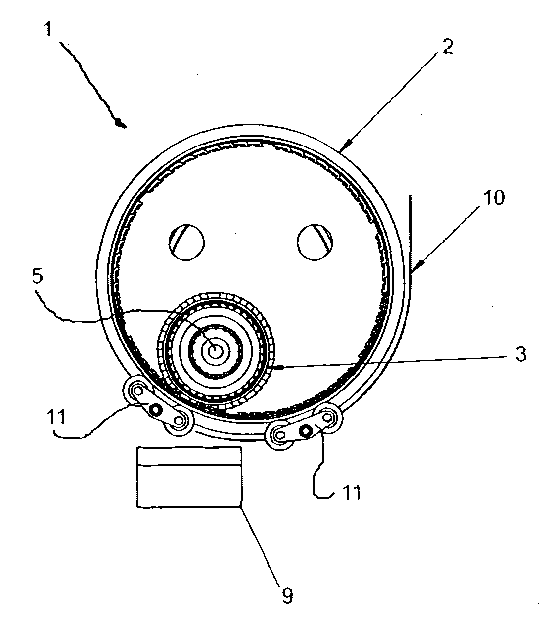
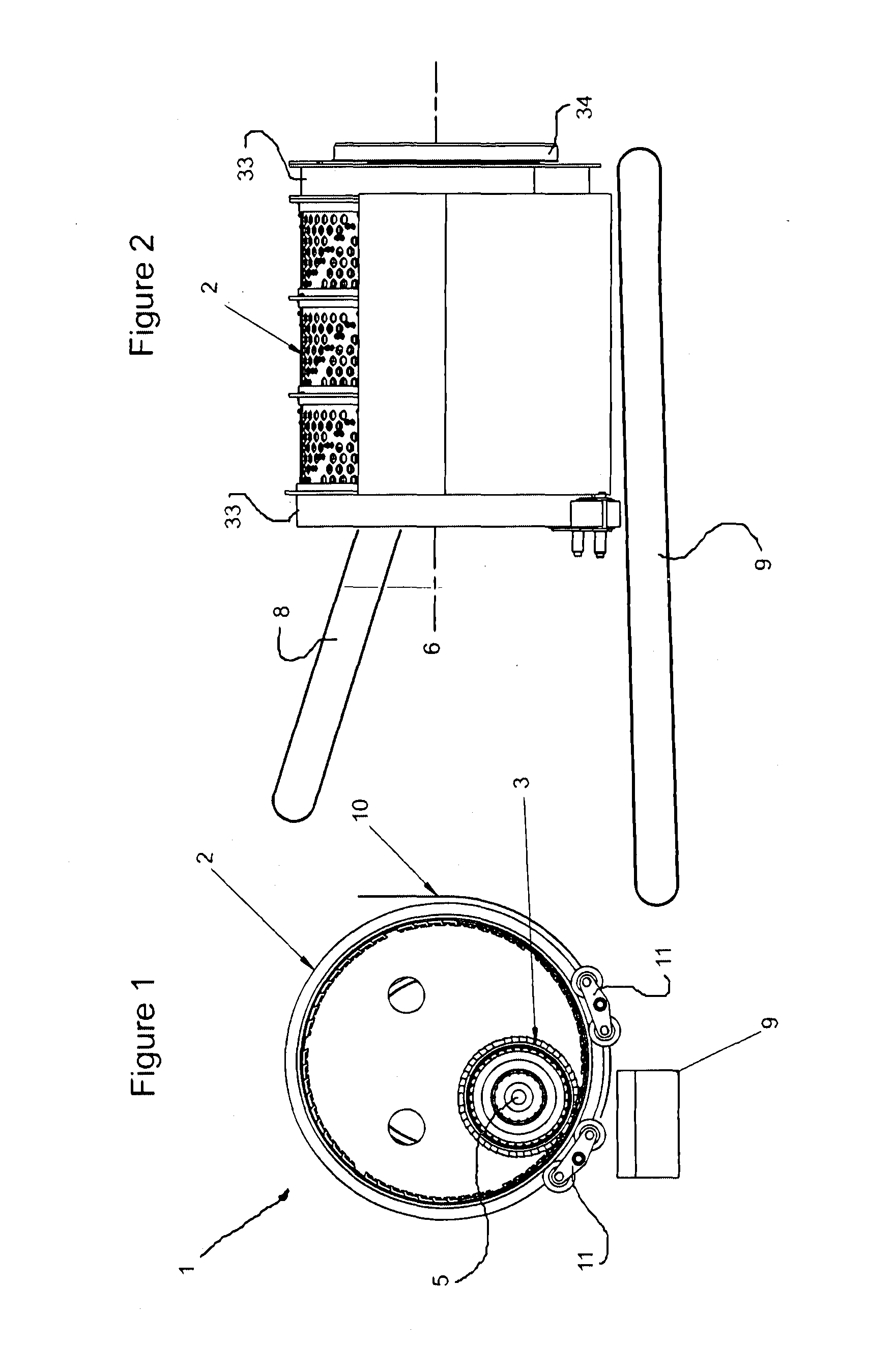
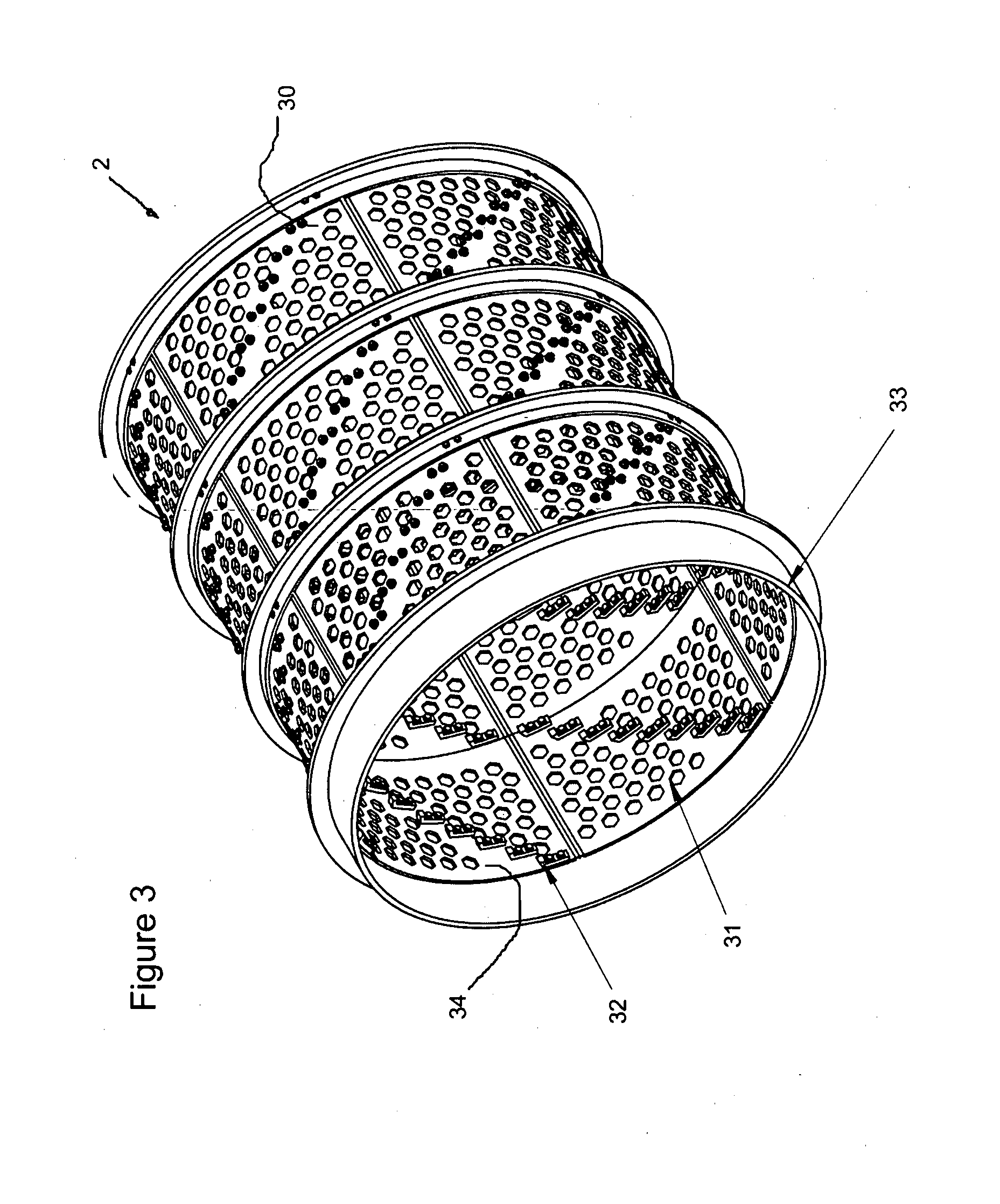
[0100]FIG. 1 illustrates comminution apparatus (generally indicated by arrow 1) comprising an outer comminution drum (2) and inner comminution drum (3). They are typically manufactured of metal, typically a suitable steel. Stainless steels may be used where appropriate.

[0101]The outer comminution drum (2) is substantially cylindrical in configuration and has a hollow portion (4) in which the inner comminution drum (3) is located.

[0102]The outer comminution drum (2) has a central longitudinal axis (6) which is also its rotational axis. The inner comminution drum (3) also has a central longitudinal axis (5) which is also its rotational axis.

[0103]Drive means (not shown for clarity) comprising either or both hydraulic or electric motors power the rotation of the inner (3) and outer (2) comminution drums substantially independently of each other (i.e. the rotational speed of one or either can be altered without affecting the rotational speed of the other). Both drums rotate clockwise in...


PUM


Abstract

Comminution apparatus is described which is tailored for the processing of green, soft, and fibrous waste. Inner and outer comminution drums bear projecting macerating features which can progressively interact to provide a shearing action on material on waste within the outer comminution drum. Screening apertures on the outer comminution drum allow for the exit of comminuted material.

Description

TECHNICAL FIELD[0001]The invention relates generally apparatus for the comminution and screening of solid materials into smaller fragments, and particularly the comminution of green waste and municipal refuse.BACKGROUND ART[0002]The applicant has previous invented apparatus for the comminution of solid materials, these being the subject of published patent applications WO / 2005 / 092509 and WO / 2006 / 093421. These inventions focus more on the comminution of firm materials such as waste wood and timber into a material commonly referred to as hog fuel, though were also able to be used for a range of other solid materials including demolition waste. The inventions relied on a rotating disk with teeth which basically chipped material as it came into contact therewith.[0003]However, a limitation of the invention was that it worked best with material which did not have a high moisture content and which responding well to a chipping action—e.g. woody and brittle materials. In practice, stringy ...

Claims


Application Information

Patent Timeline
Patent Type & Authority Applications(United States)
IPC IPC(8): B02C23/00B02C19/00
CPCB02C15/16B02C17/002B02C17/007B02C17/24B02C17/10B02C17/1805B02C17/02
Inventor SHARP, RODNEY WARWICK
Owner PROGRESSIVE IP
Why Eureka
Try Eureka