Automatic pneumatic cutting machine

A pneumatic, automatic technology, applied in the cutting of textile materials, textile and papermaking, metal processing and other directions, can solve the problems of short service life, inconvenient operation, low automation level of the cutting machine, etc., and achieve high cutting force and simple structure. , good effect

Inactive Publication Date: 2015-10-28
WUJIANG XINJIN TEXTILE
View PDF7 Cites 3 Cited by
  • Summary
  • Abstract
  • Description
  • Claims
  • Application Information

AI Technical Summary

Problems solved by technology

In the production process, the operation is inconvenient and the automation level is low
For this reason, patent 202705759U provides an electric cutting machine, but its mechanical transmission structure is complex, not only takes up a lot of space of the cutting machine, but also frequent mechanical friction, the service life of the cutting machine is short

Method used


Image

  • Automatic pneumatic cutting machine

Examples


Embodiment

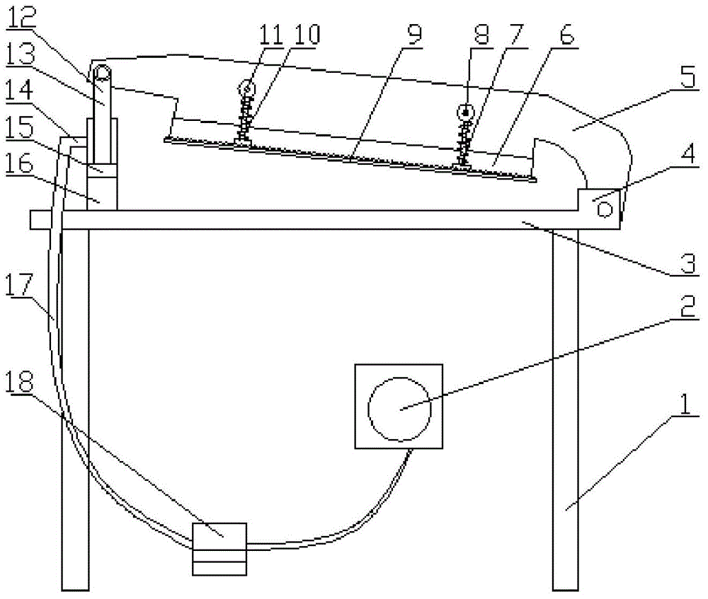
[0013] Such as figure 1 Shown, a kind of air pressure automatic cutting machine, it comprises frame 1, panel 3, knife rest 5, air pressure device 11; Panel 3 is installed on the frame 1; One side is hingedly connected with the support member 4 fixed on the panel 3, and the other side of the knife rest 5 is hingedly connected with one end of the air pressure rod 13 of the air pressure device 12; the other end of the air pressure rod 13 is installed in the air cylinder 16; The bottom of knife rest 5 is provided with blade 6, and the edge of a knife of this blade 6 is a curve; Blade 6 both sides is provided with pressing plate 9, and each pressing plate 9 links to each other with knife rest 5 by two elastic mechanisms 7 juxtaposed on both sides of pressing plate 9 Described elastic mechanism 7 is made of spring 11, fixed block 8, connecting shaft 10, and fixed block 8 is provided with through hole and is fixed on the knife rest 5, and connecting shaft 10 one end is installed on t...


PUM


Abstract

The invention relates to an automatic pneumatic cutting machine. The automatic pneumatic cutting machine comprises a machine frame, a panel, a cutter rest and a pneumatic device. The panel is installed on the machine frame. The cutter rest is arranged over the panel, one side of the cutter rest is hinged to a supporting piece fixed to the panel, and the other side of the cutter rest is hinged to one end of a pneumatic rod of a pneumatic system. The other end of the pneumatic rod is installed in a pneumatic cylinder. The pneumatic cylinder controls air generated by a pneumatic pump to enter the pneumatic cylinder through a pedal. The pneumatic system is adopted for controlling the cutter rest to move vertically to cut off leather or cloth. The pneumatic system occupies a small space of the cutting machine due to the simple structure and has a better cutting effect due to the large cutting force.

Description

technical field [0001] The invention relates to the field of cutting machines, in particular to a pneumatic automatic cutting machine. Background technique [0002] At present, the cutting machines used for leather and cloth proofing adopt manual cutting. In the production process, the operation is inconvenient and the automation level is low. For this reason, patent 202705759U provides an electric cutting machine, but its mechanical transmission structure is complicated, not only takes up the space of cutting machine in large quantities, and frequent mechanical friction, the service life of cutting machine is short. Contents of the invention [0003] In order to solve the above technical problems, the present invention provides a pneumatic automatic cutting machine. The technical solution adopted by the present invention to solve the technical problems is: a pneumatic automatic cutting machine, which includes a frame and an air pressure device, the panel is installed on...

Claims


Application Information

Patent Timeline
Patent Type & Authority Applications(China)
IPC IPC(8): B26D1/08B26D5/12D06H7/24
Inventor 施纯屿
Owner WUJIANG XINJIN TEXTILE
Why Eureka
Try Eureka