Bone resection apparatus

a bone resection and apparatus technology, applied in the field of bone resection apparatus, can solve the problems of deterioration of the patient's rotator cuff, accelerated humeral articular destruction and erosion of the acromion, and significant limitation of the patient's range of motion, and achieve the effect of eliminating painful articulation

Active Publication Date: 2009-11-03
DEPUY PROD INC
View PDF38 Cites 164 Cited by
  • Summary
  • Abstract
  • Description
  • Claims
  • Application Information

AI Technical Summary

Benefits of technology

[0012]It is moreover an object of the present invention to provide an improved apparatus for guiding a cutting tool during resection of a greater tubercle from a humerus of a patient during performance of a shoulder replacement procedure.
[0013]It is a further object of the present invention to provide a new and useful method of resecting a greater tubercle from a humerus of a patient during performance of a shoulder replacement procedure.
[0014]It is also an object of the present invention to provide an improved method of resecting a greater tubercle from a humerus of a patient during performance of a shoulder replacement procedure.
[0015]It is yet another object of the present invention to provide a method and apparatus for performing a shoulder replacement procedure which eliminates painful articulation between the greater tubercle of the humerus and the acromion.

Problems solved by technology

One such condition is the deterioration of the patient's rotator cuff.
Such articulation between these components accelerates humeral articular destruction and erosion of the acromion and acromioclavicular joint.
Moreover, such bone-to-bone contact is extremely painful for the patient thereby significantly limiting the patient's range of motion.
However, clinical experience has shown that such use of a large humeral head prosthesis “overstuffs” the shoulder joint thereby increasing soft tissue tension, reducing joint range of motion, and increasing shoulder pain.
Moreover, such use of an oversized prosthetic head fails to resurface the area of the greater tubercle of the humerus thereby allowing for bone-to-bone contact between the greater tubercle and the acromion during abduction of the patient's arm.
However, heretofore designed bipolar prosthetic heads include relatively large offsets thereby overstuffing the shoulder joint in a similar manner to as described above.
In addition, such bipolar prosthetic heads do not cover the articulating surface between the greater tubercle and the acromion thereby creating painful bone-to-bone contact therebetween.
Although this approach results in a smoother tubercle contact surface, relatively painful bone-to-bone articulating contact still occurs thereby reducing the patient's range of motion.

Method used


Image

  • Bone resection apparatus
  • Bone resection apparatus
  • Bone resection apparatus

Examples


Embodiment Construction

[0022]While the invention is susceptible to various modifications and alternative forms, a specific embodiment thereof has been shown by way of example in the drawings and will herein be described in detail. It should be understood, however, that there is no intent to limit the invention to the particular form disclosed, but on the contrary, the intention is to cover all modifications, equivalents, and alternatives falling within the spirit and scope of the invention as defined by the appended claims.

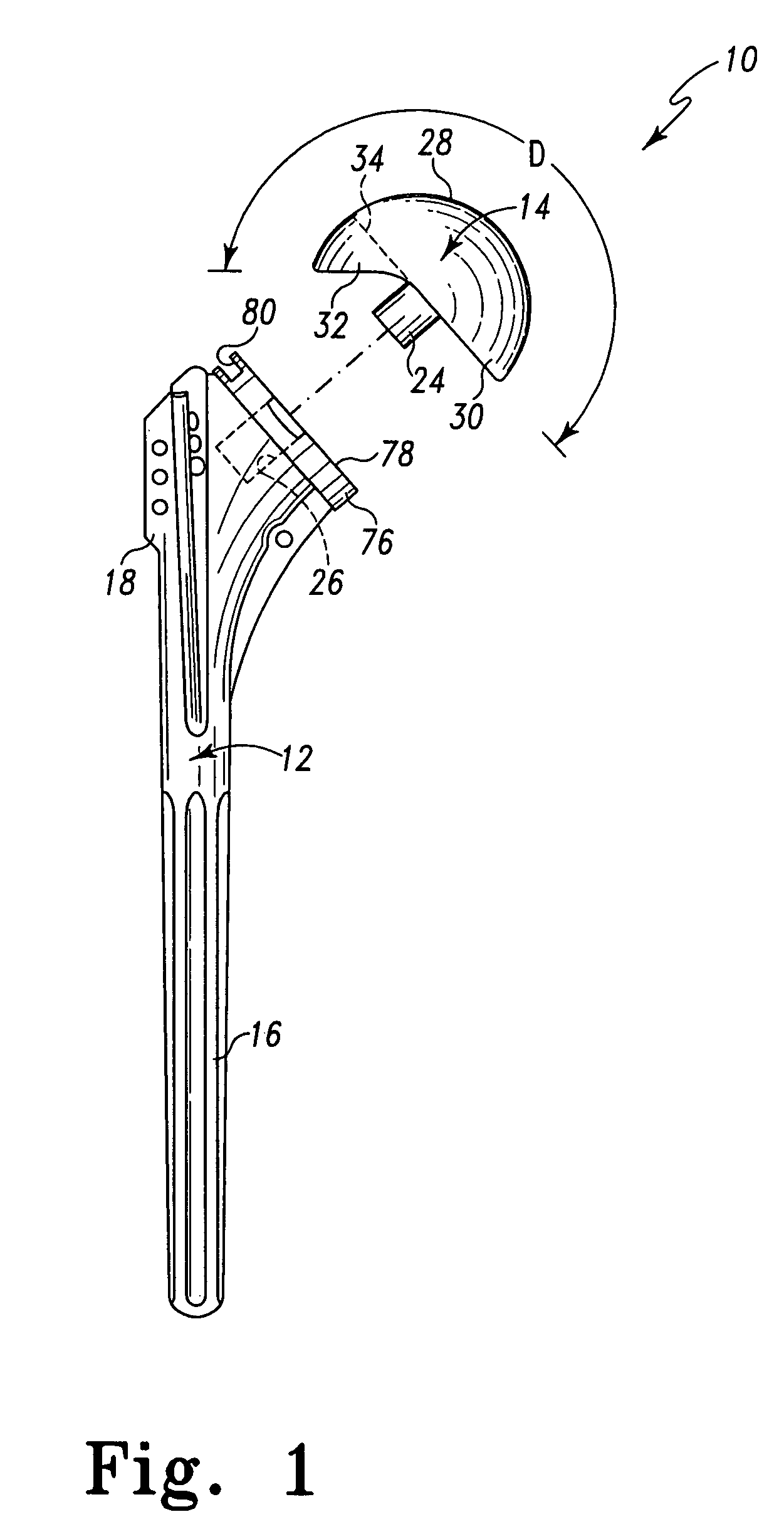
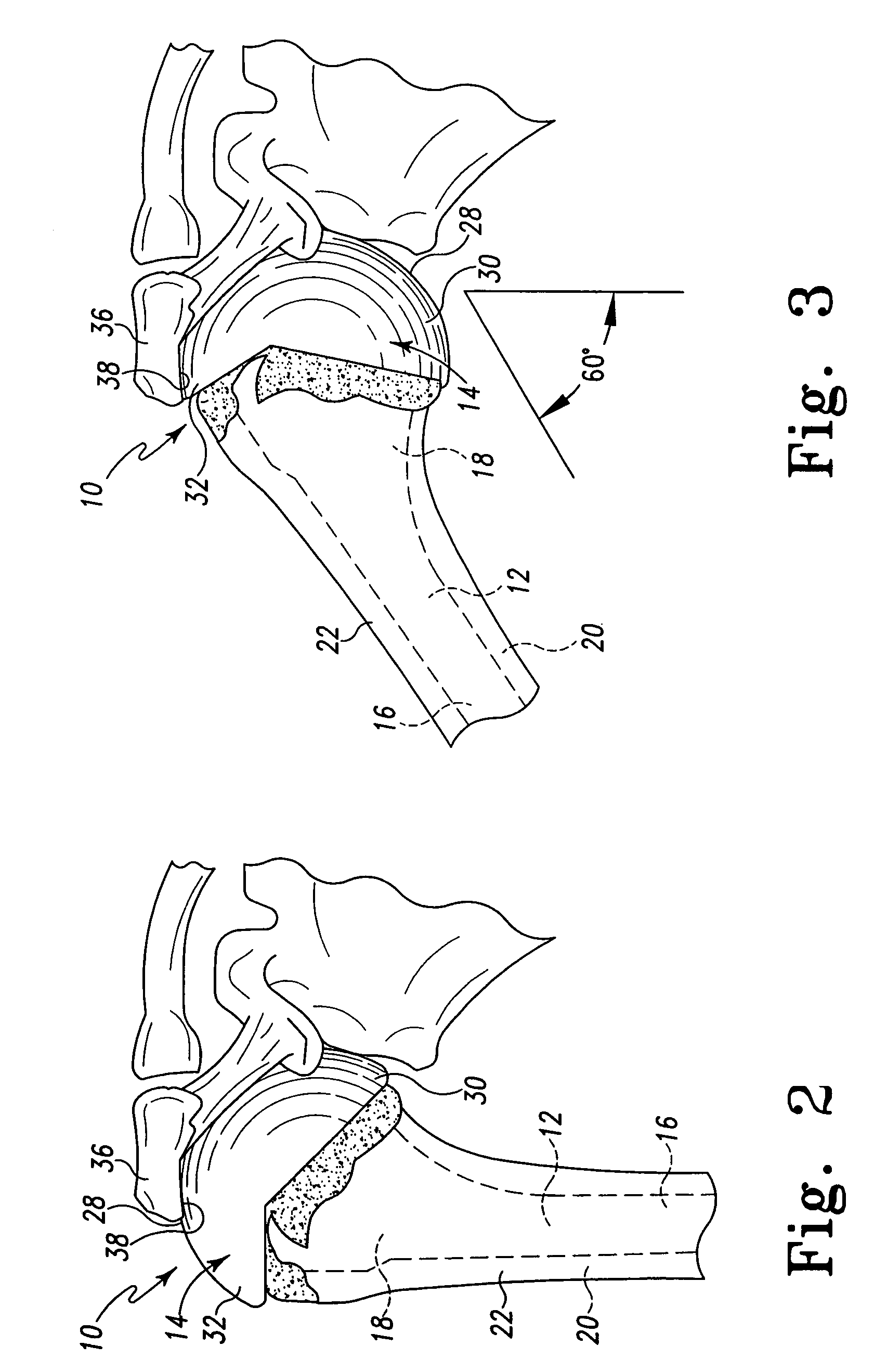
[0023]Referring now to FIGS. 1-3, there is shown a modular humeral prosthesis 10 which includes a stem component 12 and a head component 14. The stem component 12 includes an elongated stem portion 16 and a proximal body portion 18. It should be appreciated that, as used herein, the words proximal and distal are terms of reference that indicate a particular portion of a bone or prosthesis component according to the relative disposition of the natural bone or implanted prosthesis. Specif...


PUM


Abstract

A surgical assembly for resecting a greater tubercle from a humerus of a patient during performance of a shoulder replacement procedure. The surgical assembly includes a cutting tool for resecting the greater tubercle from the humerus. The surgical assembly also includes a tool guide member having a tool guide surface defined therein. The tool guide surface is configured to position the cutting tool in a predetermined position relative to the greater tubercle of the humerus.

Description

[0001]This application is a continuation of application Ser. No. 09 / 767,487, filed on Jan. 23, 2001, now U.S. Pat. No. 6,780,190 the disclosure of which is hereby totally incorporated by reference in its entirety.TECHNICAL FIELD OF THE INVENTION[0002]The present invention relates generally to a bone resection apparatus, and more particularly to an apparatus useful for resecting a greater tubercle from a humerus of a patient during performance of a shoulder replacement procedure.BACKGROUND OF THE INVENTION[0003]During the lifetime of a patient, it may be necessary to perform a joint replacement procedure on the patient as a result of, for example, disease or trauma. One such type of joint replacement procedure is a shoulder replacement procedure in which a diseased and / or damaged shoulder joint is replaced with a prosthetic shoulder joint.[0004]The need for a shoulder replacement procedure may be created by the presence of any one of a number of conditions. One such condition is the ...

Claims


Application Information

Patent Timeline
Patent Type & Authority Patents(United States)
IPC IPC(8): A61B17/00A61B17/56A61B17/15
CPCA61B17/15
Inventor MARONEY, BRIAN J.
Owner DEPUY PROD INC
Why Eureka
Try Eureka