Galvanically isolated charge balance system

a charge balance and galvanic isolation technology, applied in the direction of transportation and packaging, indicating/monitoring circuit, and arrangement of several simultaneous batteries, can solve the problem of inefficient discharge of the majority of cells, and achieve the effect of improving the galvanic isolation charge balance system

Active Publication Date: 2009-11-03
ANALOG DEVICES INC
View PDF4 Cites 31 Cited by
  • Summary
  • Abstract
  • Description
  • Claims
  • Application Information

AI Technical Summary

Benefits of technology

[0003]It is therefore an object of this invention to provide an improved galvanically isolated charge balance system.
[0004]It is a further object of this invention to provide such an improved galvanically isolated charge balance system which can employ an on-off and / or linear control for balancing charge.

Problems solved by technology

One shortcoming with this is that, in a multicell battery where only one or a few cells are under charged, it is inefficient to discharge the majority of cells to bring them down to the charge level of the few undercharged.

Method used


Image

  • Galvanically isolated charge balance system
  • Galvanically isolated charge balance system
  • Galvanically isolated charge balance system

Examples


Embodiment Construction

[0016]Aside from the preferred embodiment or embodiments disclosed below, this invention is capable of other embodiments and of being practiced or being carried out in various ways. Thus, it is to be understood that the invention is not limited in its application to the details of construction and the arrangements of components set forth in the following description or illustrated in the drawings. If only one embodiment is described herein, the claims hereof are not to be limited to that embodiment. Moreover, the claims hereof are not to be read restrictively unless there is clear and convincing evidence manifesting a certain exclusion, restriction, or disclaimer.

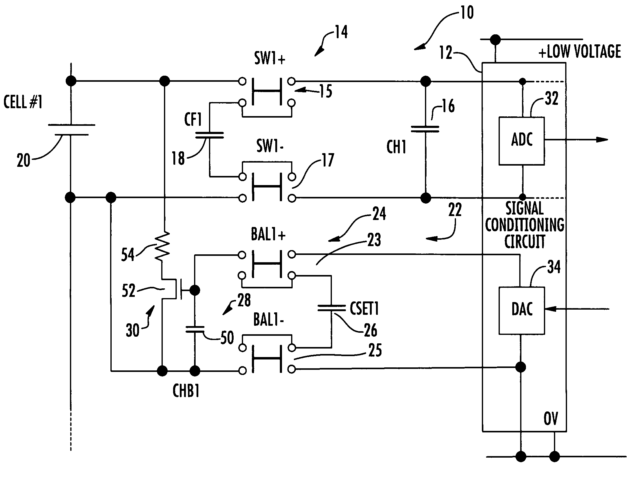
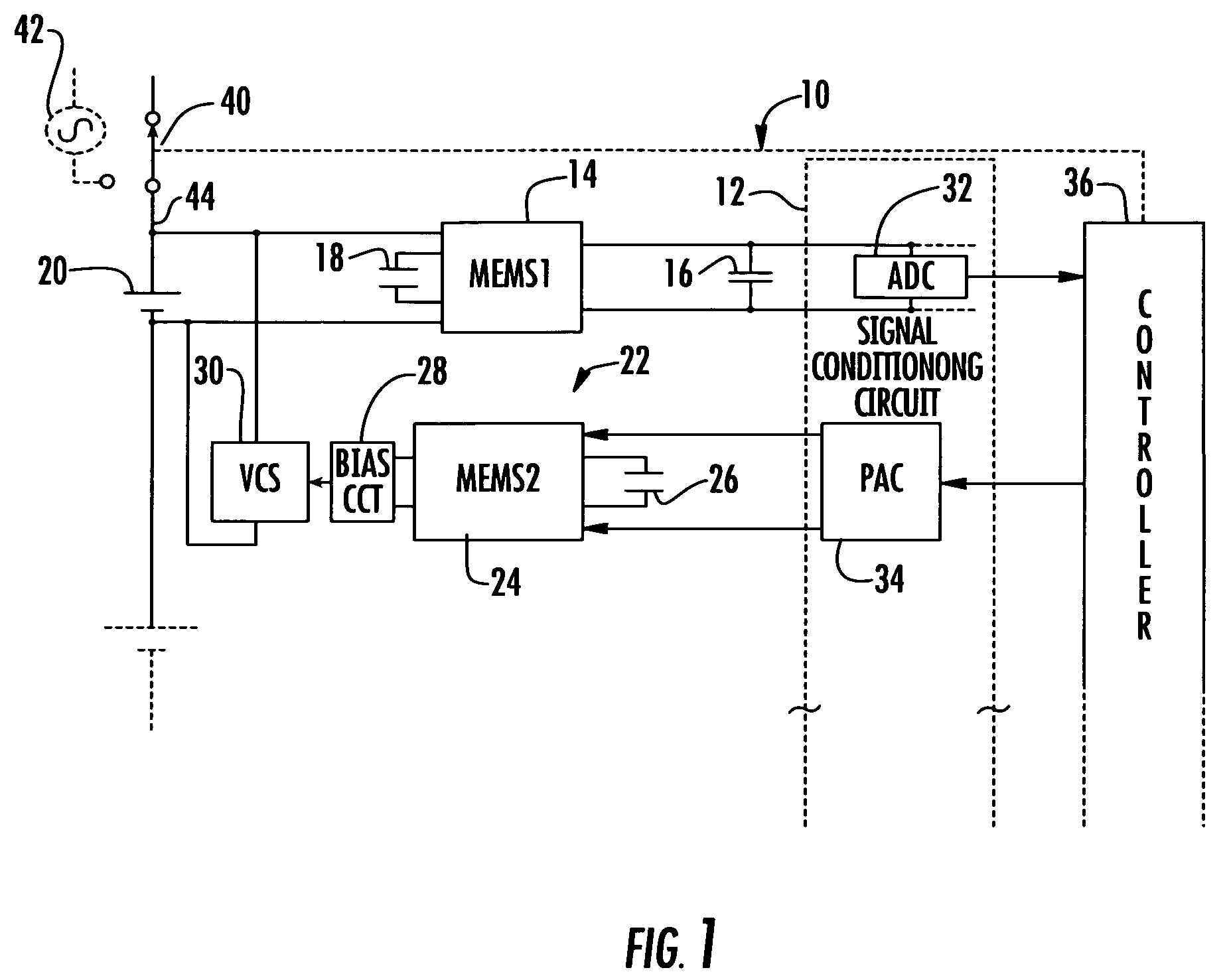
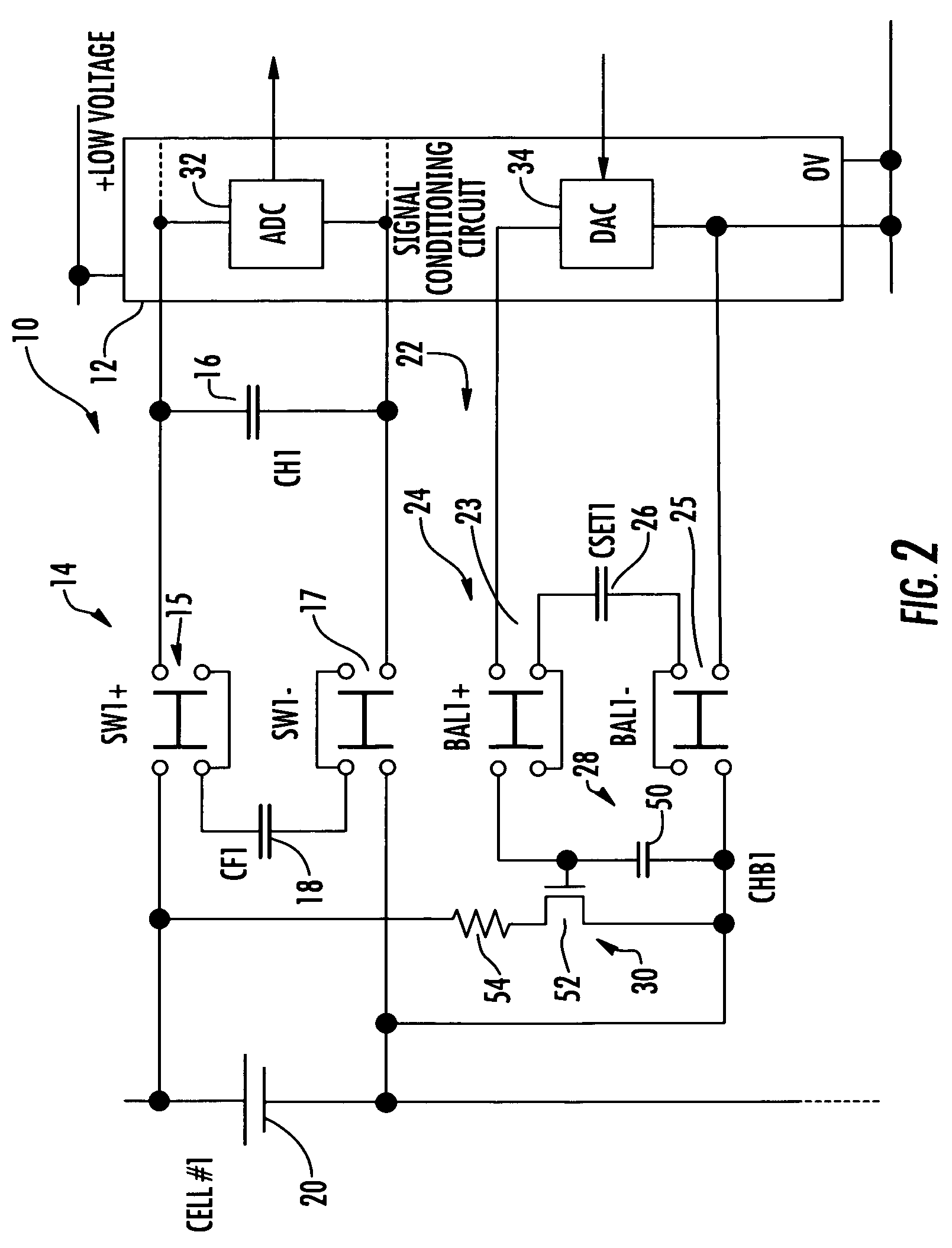
[0017]There is shown in FIG. 1 a galvanically isolated signal conditioning system 10 including signal conditioning circuit 12 and MEMS device 14 along with flying capacitor 18 and hold capacitor 16 which serves one battery cell 20 of a number of battery cells not shown. Also shown in FIG. 1 is a galvanically isolated charge...


PUM


Abstract

A galvanically isolated charge balance system for a multicell battery includes a balancing circuit associated with each cell; each balancing circuit including a flying capacitor; a variable conductance switch; and a biasing circuit for the variable conductance switch; and a galvanically isolating MEMS switching device for selectively connecting the flying capacitor to a voltage supply to charge it to a predetermined voltage and to the biasing circuit for setting the variable conductance switch to adjust the charge on its associated cell to a preselected level.

Description

FIELD OF THE INVENTION[0001]This invention relates to a galvanically isolated charge balance system.BACKGROUND OF THE INVENTION[0002]In one approach charge balancing circuits (passive) discharge one or more cells of a battery to bring all of the cells into balance to improve battery life. Typically this is done by controlling the leakage current from each cell individually. For example, a transistor switch and series resistance are configured in parallel with each cell. The switch is turned on for a predetermined time depending on the over charge of the associated cell, e.g. the greater the over charge the longer the switch is held on to continue the discharge. One shortcoming with this is that, in a multicell battery where only one or a few cells are under charged, it is inefficient to discharge the majority of cells to bring them down to the charge level of the few undercharged. Another approach (active) is to apply a charge, e.g. via a flying capacitor to the one or few cells tha...

Claims


Application Information

Patent Timeline
Patent Type & Authority Patents(United States)
IPC IPC(8): H02J7/00
CPCH02J7/0021H02J7/0016H02J7/0014H02J7/0048
Inventor WYNNE, JOHNHYNES, EAMON
Owner ANALOG DEVICES INC
Why Eureka
Try Eureka