
Dual magnetron sputtering apparatus utilizing control means for delivering balanced power

Active Publication Date: 2004-12-30
AES GLOBAL HLDG PTE LTD
View PDF2 Cites 21 Cited by
  • Summary
  • Abstract
  • Description
  • Claims
  • Application Information

AI Technical Summary

Problems solved by technology

In these applications there have been operational process difficulties attributed to asymmetrical cathode behavior.
These problems can occur with all alternating current sine generators and can be due to an unbalance in delivered power between the targets.
Possible causes of this unbalance can be due to uneven gas flows, different or uneven magnetic fields, targets with different oxidation states, or targets of different thicknesses.
For example, if the unbalance is due to different oxidation states of the two targets, one may apply more power to the target with the higher coverage of oxide, causing the oxide coating to be sputtered away on that target, rebalancing the targets.
This direct current flow subtracts from the current into one target and adds to the current in the other, resulting in an asymmetry in current levels in the two targets.
However, even with this charge balance, unbalanced power delivery may occur, since a net charge may accumulate on the capacitor, resulting in a difference in voltage between the two targets.
To date, although this problem has generally been recognized in the industry, no one has proposed an adequate solution.

Method used


Image

  • Dual magnetron sputtering apparatus utilizing control means for delivering balanced power
  • Dual magnetron sputtering apparatus utilizing control means for delivering balanced power
  • Dual magnetron sputtering apparatus utilizing control means for delivering balanced power

Examples


Embodiment Construction

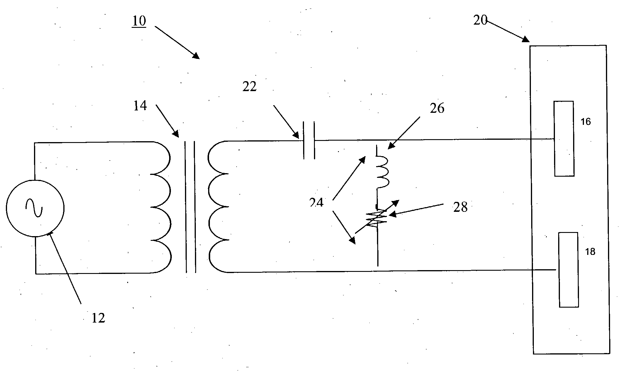
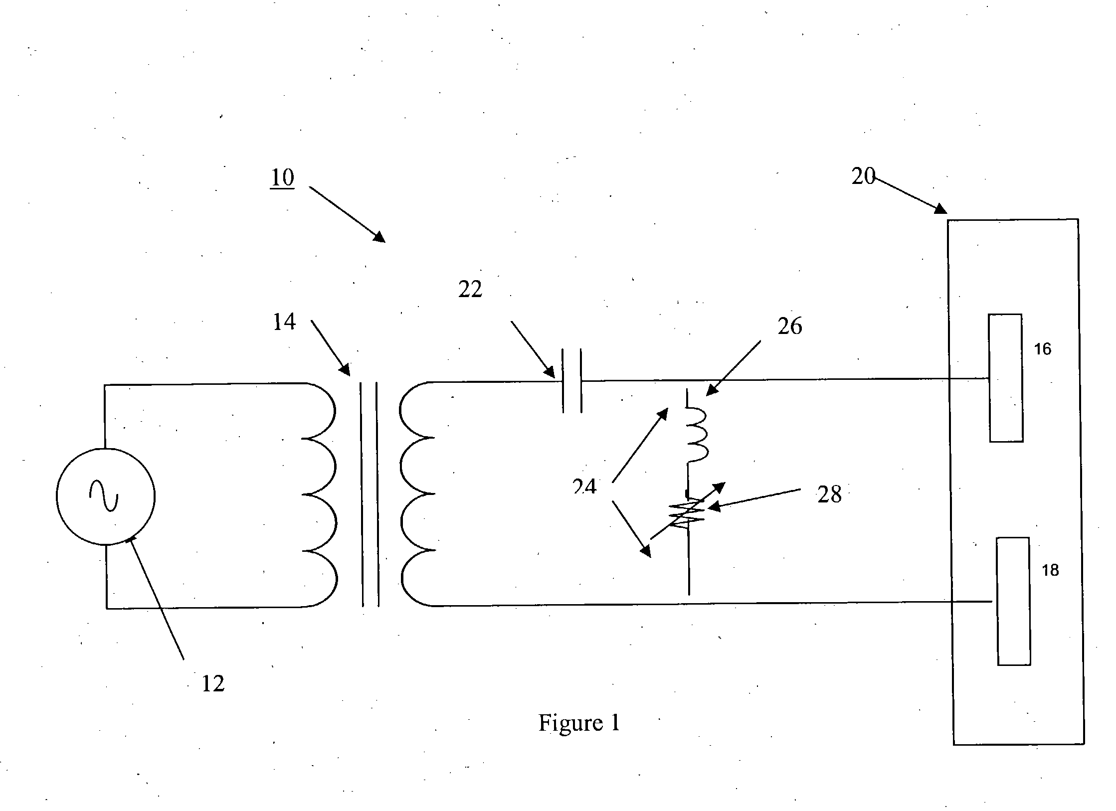
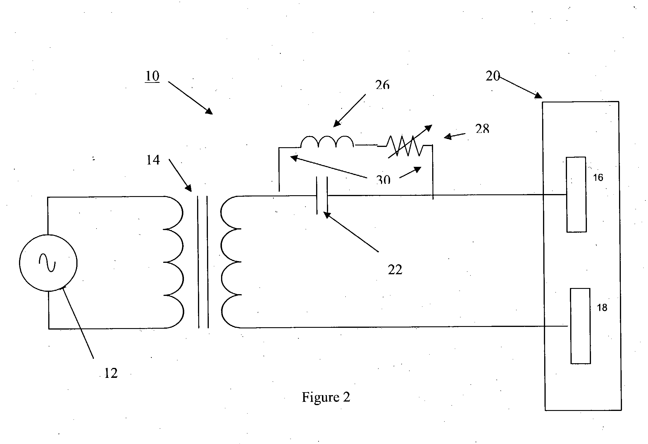
[0015] There is shown in FIG. 1 a reactive dual magnetron sputtering system 10 that incorporates the principles of this invention. The power source is generally comprised of an ac generator 12 connected to the primary of a transformer 14 with its secondary output connected to dual targets 16 and 18 mounted in a plasma chamber 20. A blocking capacitor 22 is placed in series with the target loads 16 and 18 to prevent the flow of de current to the target loads. A balancing circuit 24 is placed in parallel with the blocking capacitor 22 across the secondary of the transformer. The balancing circuit 24 is comprised of an inductor 26 and a variable resistor 28 that shunts the direct current and prevents some dc voltage from being applied to the dc blocking capacitor 22.

[0016] FIG. 2 illustrates reactive dual magnetron sputtering systems such as 10 that utilize an ac generator of the parallel-resonant type that do not include a blocking capacitor such as 22 and behaves as an ac voltage sou...


PUM

PropertyMeasurementUnit
Electric potential / voltageaaaaaaaaaa
Erosion-corrosion rateaaaaaaaaaa

Abstract

There is disclosed a dual magnetron sputtering apparatus that is comprised of a balancing circuit connected to the output of an ac power source that supplies ac power to at least two target materials such that the balancing circuit allows the power supply to deliver equal power to each target material. In those applications where there may be an erosion of one target material faster than the other, the balancing circuit allows the power supply to deliberately unbalance the power to at least one of the target materials to reduce power to the target to compensate for faster erosion of the target.

Description

[0001] 1. Field of the Invention[0002] This invention relates generally to ac high power supplies designed specifically for use in a plasma environment. These power supplies provide wide-range, mid frequency sinusoidal process power for dual-magnetron sputtering. More particularly this invention relates to a dual magnetron power supply that utilizes a control means for delivering controlled balanced power to dual targets to achieve even deposition rates to both targets or uneven deposition rates if so desired.[0003] 2. Brief Description of the Prior Art[0004] AC dual magnetron power supplies are ideally suited for large-area glass coating applications such as architectural, automotive, anti-reflective, and mirrors. In these applications there have been operational process difficulties attributed to asymmetrical cathode behavior. Symptoms include coat-over of one target in a pair or radically different erosion rates in a target pair. These problems can occur with all alternating curr...

Claims


Application Information

Patent Timeline
IPC IPC(8): C23C14/35H01J37/34
CPCC23C14/352H01J37/3405H01J37/3444
Inventor SEYMOUR, ERIC A.PRATT, ANNABELLE
Owner AES GLOBAL HLDG PTE LTD
Learn More