
Stretcher with brake mechanism

a technology of a brake mechanism and a stretcher, which is applied in the field of stretchers, can solve the problems of affecting the mobility of patients, and unable to evacuate the building on their own, and achieves the effect of convenient unfolding

Inactive Publication Date: 2009-11-10
SCOPRA SCI & GENIE SEC
View PDF15 Cites 5 Cited by
  • Summary
  • Abstract
  • Description
  • Claims
  • Application Information

AI Technical Summary

Benefits of technology

[0010]In another aspect, the present invention provides a brake mechanism on a stretcher that progressively increases the amount of friction between the stretcher and the surface on which the stretcher is supported, to reduce or stop movement of the stretcher.
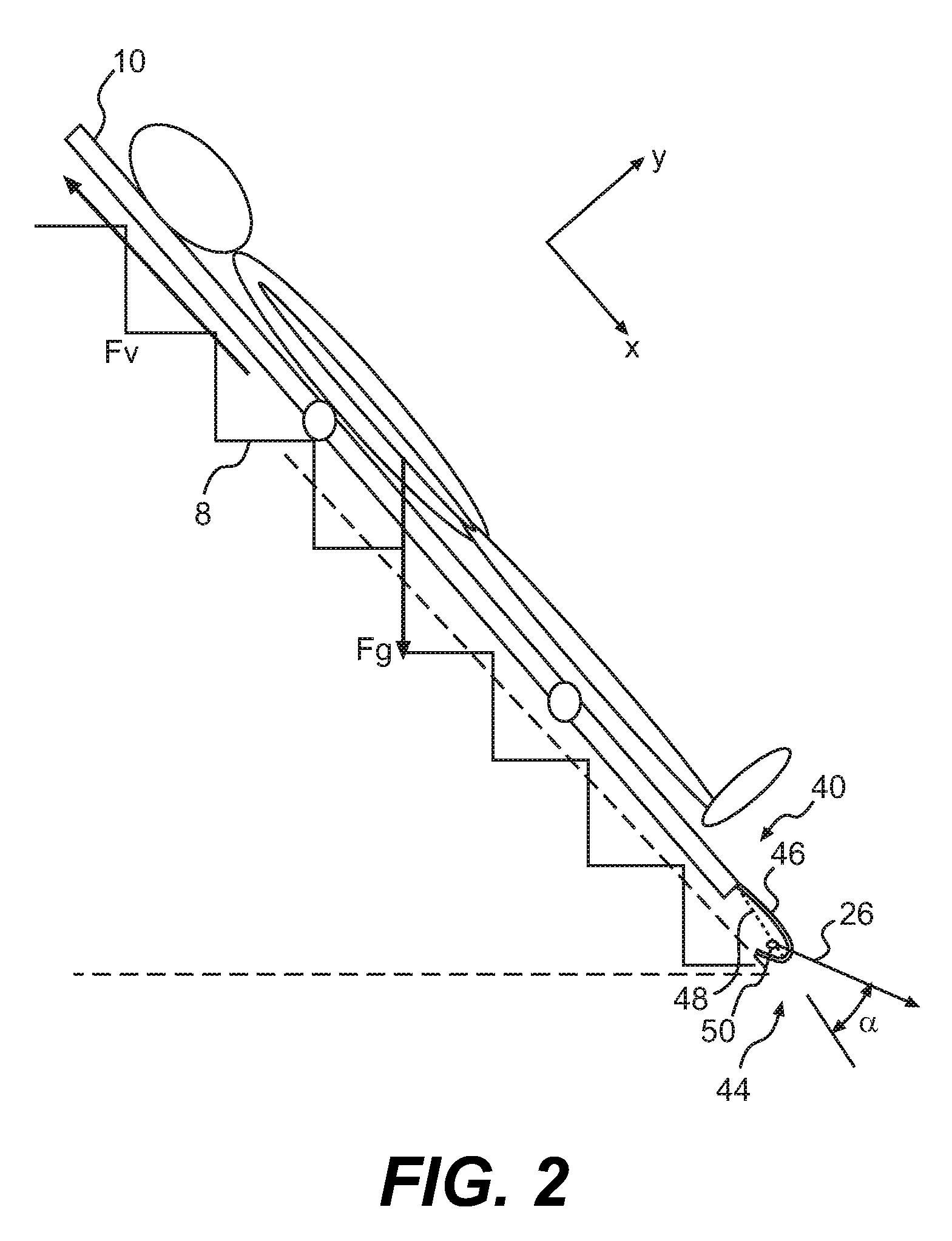
[0011]In one other aspect, the present invention provides a stretcher having a pulling member influencing the position or the activation of the brake mechanism on the stretcher. When a person pulls on the pulling member less friction is provided, conversely, when there is less tension on the pulling member more friction is provided to provide more stability of the stretcher, particularly on an inclined surface. The angle between the pulling member and the stretcher also has an effect on the engagement or disengagement of the brake mechanism on the stretcher. Under normal conditions the brake mechanism is disengaged when the pulling member is at a certain angle with the stretcher (within a range) and engages if the pulling member is on either side of the predetermined angle.
[0012]Another aspect of the present invention provides a stretcher having a brake mechanism adapted to engage stairs and progressively move along the bottom side of the stretcher to progressively increase the amount of friction between the stretcher and the stairs.
[0014]In one other aspect of an embodiment described therein, the present invention provides a size reduction mechanism requiring limited storage space for the stretcher, when the stretcher is not in use in the patient room or in a storage room. The size reduction mechanism allows the stretcher to fold over onto itself and easily be unfolded without requiring any tools.
[0015]Another aspect of embodiments described herein provides a foot restraint to secure the feet of the patient on the stretcher and may offer additional volume to carry additional material with the patient.
[0016]A still further aspect of the present invention is to provide a stretcher with a braking system that is durable, simple in construction and economical to manufacture.

Problems solved by technology

This represents a major challenge because most patients have diminished physical capability and cannot evacuate the building on their own.
This is particularly difficult in building having several floors.
Furthermore, a stretcher in a staircase may easily become cumbersome and may prevent other people from using the stairs during the evacuation process.
Conversely, a stretcher that slides directly on the stairs in a staircase might become difficult to control during emergency evacuation.
If the stretcher goes down the stairs too quickly the patient may get an uncomfortable ride.
They will spend most of their time in a patient's room in storage and should take a limited amount of space.
However, since a stretcher needs to be assembled in a short period of time, the time to assemble the stretcher and the complexity of the assembly should be limited to a minimum.
Conventional stretchers, while adequate for their intended purposes, are not optimal.

Method used


Image

  • Stretcher with brake mechanism
  • Stretcher with brake mechanism
  • Stretcher with brake mechanism

Examples


Embodiment Construction

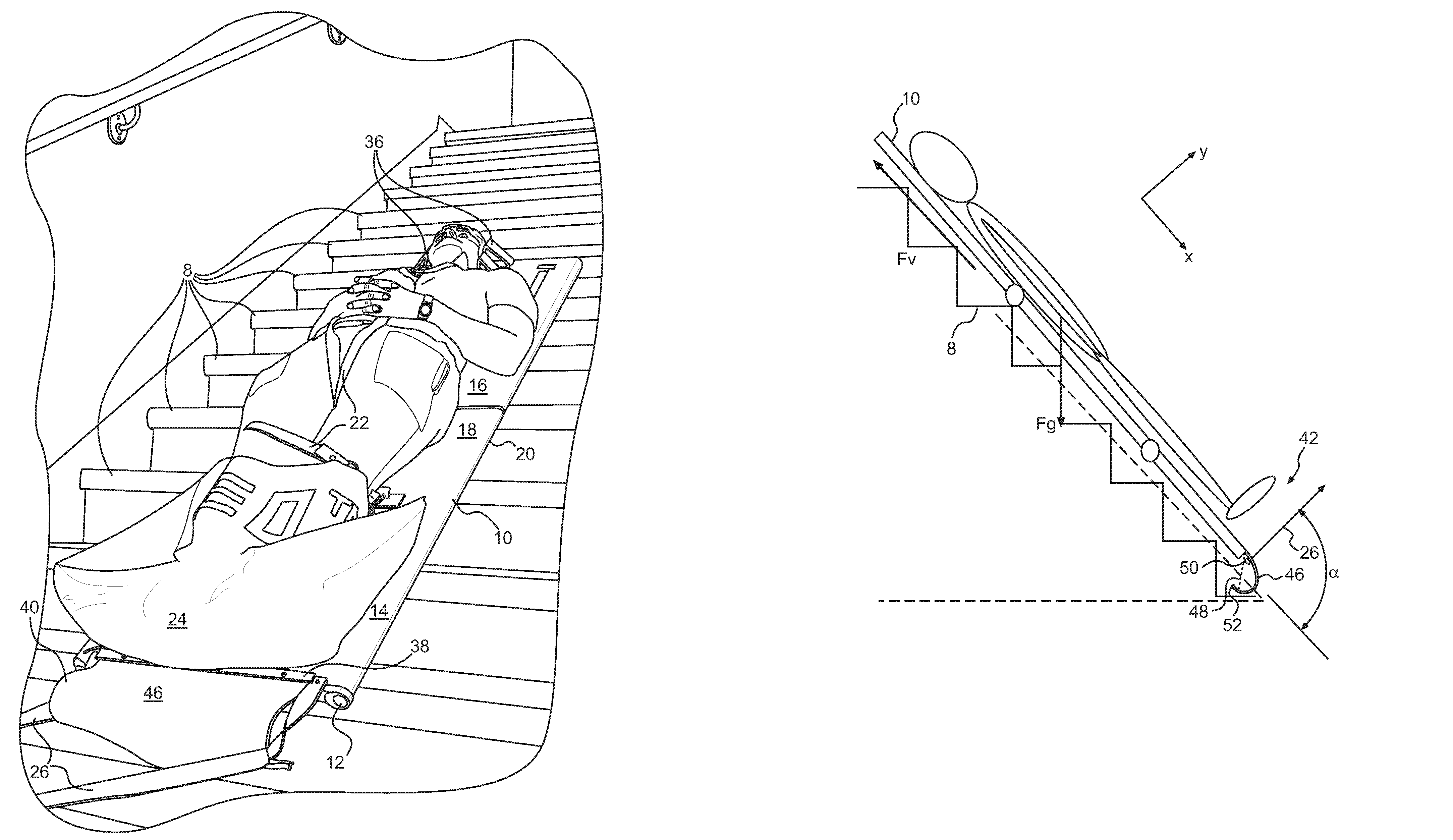
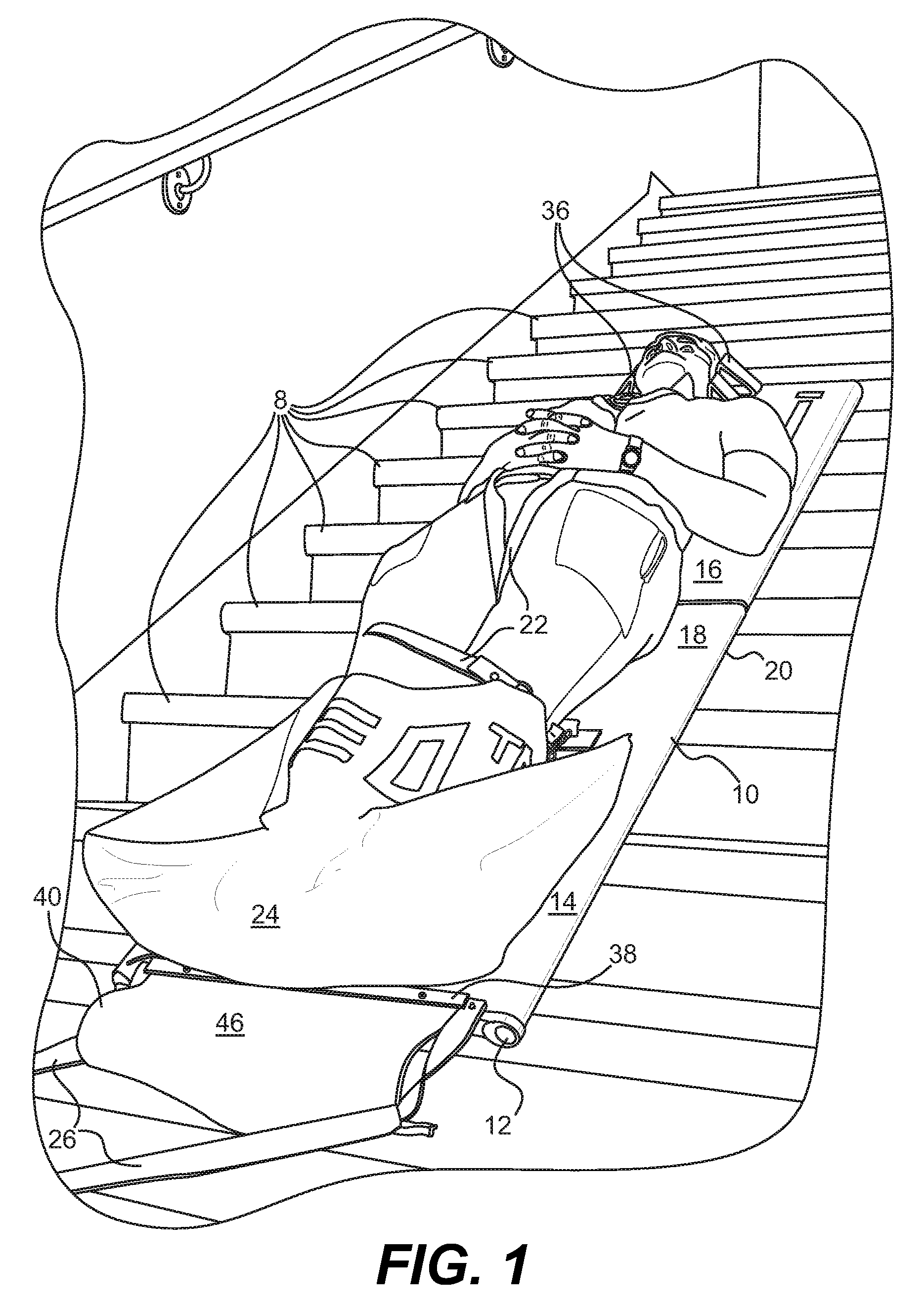
[0025]Referring to FIG. 1, there is illustrated a stretcher 10 accommodating a patient and disposed over stairs 8 in a staircase. The stretcher 10 has a top side 18 adapted to accommodate a person and a bottom side 20, opposite to the top side 18, adapted to contact a ground. The patient is secured on the top side 18 of the stretcher 10 with various body restraints 22, head restraints 36 and feet restraint 24. In a preferred embodiment, the body restraints 22 and head restraints 36 are respectively made of belt material and aluminium, but could also be any other suitable material such as plastic material. The feet restraint 24 prevents the patient significantly from moving on the stretcher 10 when the stretcher 10 is at an angle in a staircase. Preferably, the feet restraint 24 is made of textile material and is larger than the actual volume required to receive the feet of the patient. Because of its larger size, the feet restraint 24 allows room for inserting the patient's feet and...


PUM


Abstract

The present invention provides a stretcher having a brake mechanism that can be selectively activated to influence the movement of the stretcher supported by an inclined surface. The brake mechanism of the stretcher progressively increases the amount of friction between the stretcher and the surface of which the stretcher is supported to reduce or stop movements of the stretcher. The stretcher further includes a pulling member influencing the position or the activation of the brake mechanism on the stretcher and high friction means associated with the bottom side of the stretcher. The present invention also provides a size reduction mechanism requesting limited storage space for the stretcher when not in use and a foot restraint to secure the feet of the patient on the stretcher and offer additional volume to carry additional material with the patient. A method for braking a stretcher on an inclined plane is also disclosed.

Description

CROSS REFERENCE[0001]The present application claims priority to U.S. provisional patent application Ser. No. 60 / 868,785 filed Dec. 6, 2006, the entirety of which is incorporated herein by reference.FIELD OF THE INVENTION[0002]The present invention relates to a stretcher for moving a person with reduced physical capabilities, and in particular to a stretcher having a brake mechanism to slow down or stop movement of the stretcher when the stretcher is supported by an inclined surface.BACKGROUND OF THE INVENTION[0003]Hospitals and long-term care facilities must have an evacuation plan in case of emergency. They need to efficiently evacuate the patients very rapidly. This represents a major challenge because most patients have diminished physical capability and cannot evacuate the building on their own. Some patients need to be transported out of the building by other people. This is normally done using a stretcher to carry the patient. The patient is secured to the stretcher before mov...

Claims


Application Information

Patent Timeline
Patent Type & Authority Patents(United States)
IPC IPC(8): A61G1/013A61G1/04A61G1/044
CPCA61G1/04A61G1/013Y10S5/925
Inventor BEAUDRY, BENOITBASTIEN, HUGOBERGERON, FRANCOISGOSSELIN, JEAN-SÉBASTIENPOULIN, ETIENNEDESCHAMPS-SONSINO, VINCENTSEGUIN-TREMBLAY, NOEMIE
Owner SCOPRA SCI & GENIE SEC
Learn More