Extendable strap device

a strap device and strap technology, applied in the direction of travel carriers, travelling articles, other accessories, etc., can solve the problems of unfavorable hygiene, unfavorable operation using both hands, and unseemly appearance, and achieve the effect of convenient extension, convenient operation and simple structur

Inactive Publication Date: 2009-11-10
KAWAKITA KIJURO
View PDF19 Cites 3 Cited by
  • Summary
  • Abstract
  • Description
  • Claims
  • Application Information

AI Technical Summary

Benefits of technology

[0008]An object of the present invention is to overcome the inconvenience of the related art and provide a new strap having a structure which enables the strap to be shortened or accommodated by a single-handed operation.
[0011]According to the second aspect of the invention, the strap device can be easily extended to a length more than three times longer than the contracted length. When the strap is not utilized, the strap device can be contracted to a length which does not cause any trouble. When the strap is needed, it can be quickly extended to a sufficient length. In particular, since it is possible to pull only one guide to perform the contracting operation, it is easy to operate. Because the strap device of the invention has only one strap and only one connecting point between the strap and the guide, it results in a simpler structure and is less expensive in terms of manufacturing costs than the strap device of Japanese Patent No. 3359627. When the new strap used as a shoulder strap is extended, the guides do not touch the user's body because the guides are located at opposite ends of the strap. Further, it has simple design. As shown in FIG. 8, it may form a ring-like strap to be used as a mobile-phone strap, by sliding one slider to contact the other slider.

Problems solved by technology

However, when the shoulder strap is not used, the shoulder strap hangs down from the main body of the bag, which gives an unseemly appearance.
Further, there some problems in which the shoulder strap hanging down from the main body of the bag may be caught by any object or obstacle, possibly resulting in an accident in some cases and in which the shoulder strap contacts with the floor, which is unfavorable in view of hygiene.
Further, when it is accommodated (contracted), an inconvenient operation using both hands is necessary to part the two sliders from each other.
Because ordinary ring-like straps do not change in length, they are not convenient although it has a clip on the end of the strap.
A coil-like strap which is extendable is commercially available, but it cannot support a phone when a portion of the coil-like strap is held, like the ring-like strap.

Method used


Image

  • Extendable strap device
  • Extendable strap device
  • Extendable strap device

Examples


first embodiment

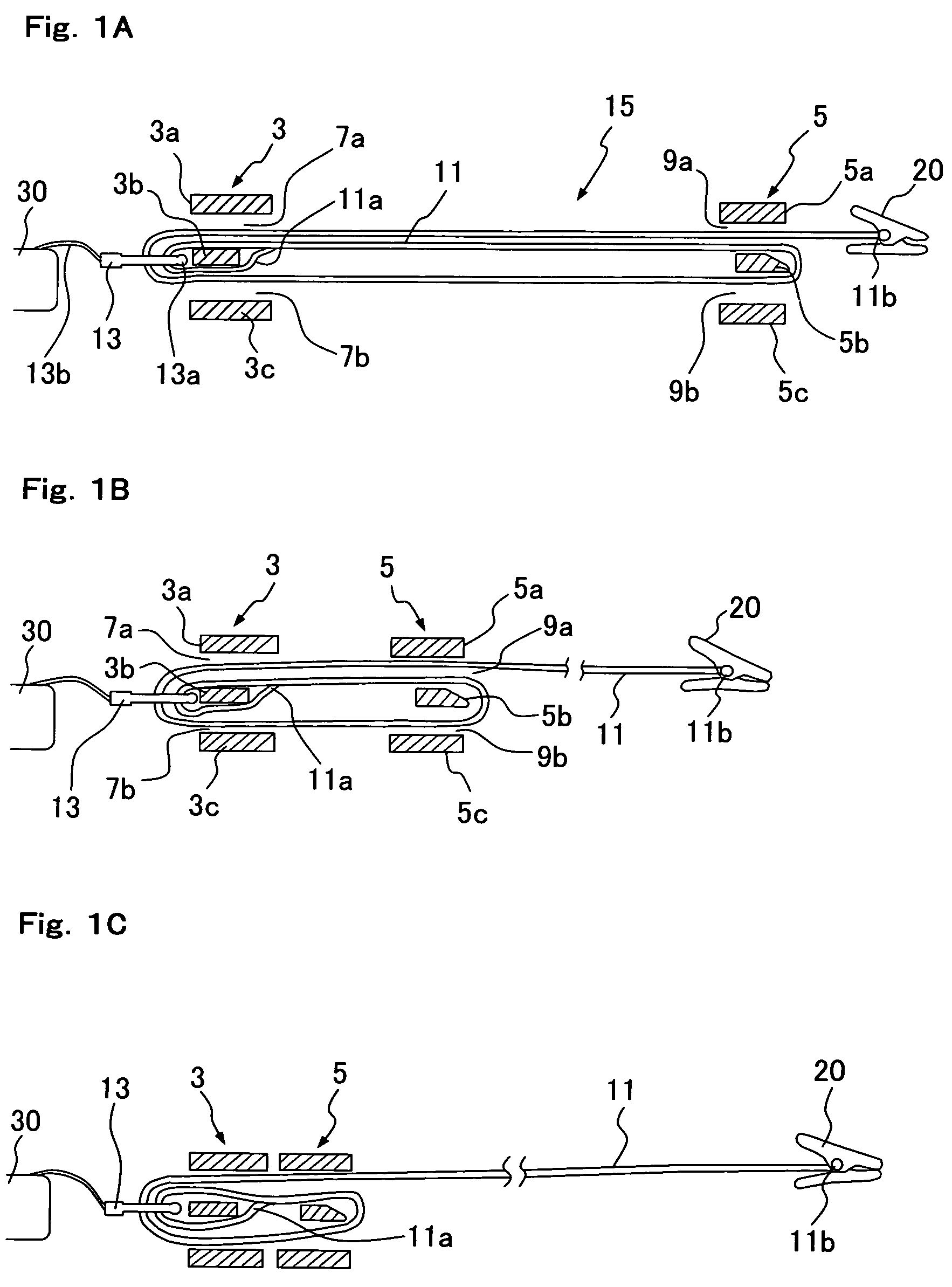
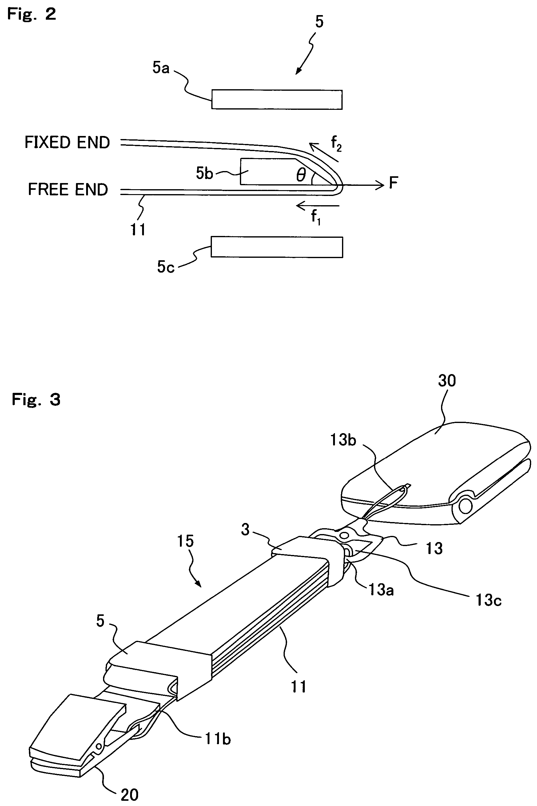
[0021]A first embodiment of the strap of the present invention will be explained with reference to FIGS. 1A to 1C, 2, and 3. A strap device 15 comprises a first guide 3, a second guide 5, a strap (strap tape) 11, and a connecting ring 13. A first end 11a of the strap 11 is secured to the first guide 3, and the other end 11b of strap 11 is secured to clip 20.

[0022]The first guide 3 is connected to an object, like a mobile-phone 30 through ring 13 and string 13b. The ring 13 has an opening 13c formed thereon, through which the strap passes (See FIG. 3). The ring may have any shape, such as circular or rectangular.

[0023]As shown in FIG. 1A and 3, the first guide 3 is a substantially rectangular frame (hollow or box structure), and a slit 7a is formed between an upper surface 3a and a central portion (intermediate part) 3b and a slit 7b is formed between a lower surface 3c and the central portion 3b. The slits 7a, 7b and the central portion 3b extend parallel to each other in a lengthwi...

second embodiment

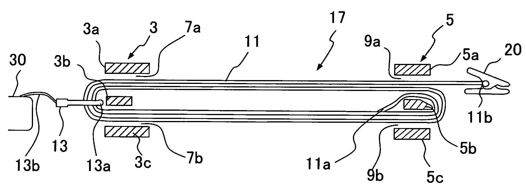
[0034]A second embodiment of the strap of the present invention will be explained with reference to FIGS. 4A and 4B. The strap device 17 is basically the same as that in the first embodiment except that the first end 11a of the strap 11 is secured to the central portion 5b of the first guide 3 and the strap 11 is presented between the first guide 3 and the second guide 5 in the form of four layers. In device 17, the other end 11b of the strap 11 passes through the slit 7b of the first guide 3, the opening 13c of the ring 13 and the slit 7a toward the second guide 5, and then passes through the slits 9a and 9b toward the first guide 3. Subsequently, the other end 11b passes through the slit 7b, the opening (13c) of the ring 13 and the slit 7a again to finally return to the second guide 5 and passes through the slit 9a to reach the position as shown in FIG. 4A.

[0035]In the strap device 17, by pulling the clip 20 away from the second guide 5, the second guide 5 approaches the first gui...

third embodiment

[0036]A third embodiment of the strap of the present invention will be explained with reference to FIGS. 5A and 5B. The strap device 19 is basically the same as that in the first embodiment except that strap 11 runs around the first guide 3 and the second guide 5 so as to overlap in five layers. In the device 19, the one end 11a of the strap 11 is secured to the first central portion 3b and the end 13a of the ring 13, and the other end 11b of the strap 11 passes through the slits 9a,9b, the slit 7b, the opening (13c) of the ring 13 and the slit 7a to go around (one round), and then passes through the slits 9a, 9b, the slit 7b, the opening (13c) of the ring 13 and the slit 7a, to go around (second round), and finally passes through the slits 9a, 9b, the slit 7b, the opening (13c) of the ring 13 and the slit 7a, to go around (third round), and goes out of the slit 9a to reach the position as shown in FIG. 5A. This strap device 19 realizes a strap extendable five times the distance bet...


PUM


Abstract

A strap device has a first guide having a first slit (7a), a third slit (7b), and an intermediate member (3b) defined therebetween; a single strap (11) connected at one end to the intermediate member (3b); and a second guide (5) that is movably provided opposite the first guide (3), on which a second slit (9a) and a fourth slit (9b) are formed, and that has an intermediate member (5b) defined between the second and fourth slits. The other end (11b) of the strap passes through the second slit (9a), the fourth (9b), third (7b), first (7a), and second (9a) slits in that order. When the other end (11b) of the strap is drawn away from the second guide (5), the strap is pulled out to three times the original length, and when the second guide (5) is drawn away from the first guide, the strap becomes the original length.

Description

CROSS-REFERENCE[0001]This application is a Continuation Application of International Application No. PCT / JP2005 / 000554 which was filed on Jan. 12, 2005 claiming the conventional priority of Japanese patent Application No. 2004-035755 filed on Jan. 12, 2004.BACKGROUND OF THE INVENTION[0002]1. Field of the Invention[0003]The present invention relates to an extendable / contractible strap device which is usable for a mobile-phone or a bag.[0004]2. Background of the Invention[0005]A bag, to which a shoulder strap (shoulder belt) is attached, is convenient, for example, when the load of a bag is heavy or when the hands of a user are intended to be made free, because the bag can be retained by hanging the shoulder strap on the shoulder. However, when the shoulder strap is not used, the shoulder strap hangs down from the main body of the bag, which gives an unseemly appearance. Further, there some problems in which the shoulder strap hanging down from the main body of the bag may be caught b...

Claims


Application Information

Patent Timeline
Patent Type & Authority Patents(United States)
IPC IPC(8): A45C13/26A45C13/30A45F3/02
CPCA45C13/30A45F3/02Y10S224/908Y10S224/93
Inventor KAWAKITA, KIJURO
Owner KAWAKITA KIJURO
Why Eureka
Try Eureka